
BE5V Installation Instructions
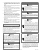
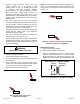
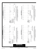
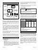
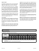
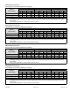
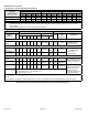
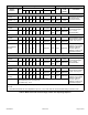
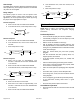
Table Of Contents
- BE5V Unit Dimensions – Upflow – Inches (mm)
- Shipping and Packing List
- General
- Requirements
- Installation Clearances
- Installation
- Condensate Drain
- Duct System and Filters
- Brazing Refrigerant Lines
- Sealing the Unit
- Electrical Connections
- BDC3 Blower Control
- Adjusting the Blower Speed
- Blower Performance
- Check-out Procedures
- Maintenance
- Repairing or Replacing Cabinet Insulation
- Professional Maintenance
- Use of Air Handler During Construction

507789-01BIssue 1818Page 16 of 24
Adjust Jumper
The ADJUST pins allow the motor to run at normal speed,
slightly higher (approximately 10%) than normal speed, or
slightly lower (approximately 10%) than normal speed.
The blower performance tables list three rows (+, NORMAL,
and -) with their respective CFM volumes. Notice that for
the 1.5 ton unit, for example, that the normal adjustment
setting for heat speed position #4 is 1050 CFM. The +
adjustment setting for that position is 1150 CFM and for
the - adjustment setting is 950 CFM. After the adjustment
setting has been determined, choose the remaining speed
jumper settings from those offered in the table in that row.
The TEST pin is available to bypass the BDC3 control and
run the motor at approximately 70% to test that the motor is
operational. This is benecial primarily in troubleshooting.
G must be energized for motor to run.
Cool Jumper
The COOL jumper is used to determine the CFM during
either cooling or heat pump operation without a call for
electric heat. These jumper selections are activated
for cooling when Y2 and DS terminals in the BE5V are
energized. The are activated for heating when Y2 is
energized.
Applications without the Comfort Sync
®
thermostat will
provide 70% of the COOL CFM during rst-stage cooling
for two-stage outdoor units. 100% of COOL speed is
provided for systems with a single-stage outdoor unit.
Applications with the Comfort Sync
®
thermostat, but no
demand for de-humidication will operate as follows:
during a rst-stage cooling call (two-stage outdoor unit),
the air volume is 70% of the COOL jumper selection. This
arrangement provides for additional dehumidication during
standard rst-stage cooling. See the blower performance
tables for various scenarios concerning use of the Comfort
Sync
®
thermostat and the BE5V series unit.
For applications with zone control, the air handler CFM
volume is determined by the control center. The minimum
blower speed is predetermined at 250 CFM for -018, -024,
-030 and -036 units and 450 CFM for -042, -048 and -060
units. This speed is not adjustable. See footnotes in the
blower performance tables.
With the thermostat set for Continuous Fan and without a
call for heating or cooling, the BE5V provides 50% of the
COOL CFM selected.
NOTE: For two-stage heat pumps, air handler will operate
at 70% of the COOL selection until supplemental electric
heat is demanded. At that time, the air handler will operate
at the selected HEAT speed. This arrangement provides
warmer supply air during second-stage heating.
Blower Performance
BE5V24 Blower Performance
0 through 0.80 in. w.g. External Static Pressure Range
ADJUST
Jumper Setting
Jumper Speed Positions
“HEAT” Speed First Stage “COOL” Speed Second Stage “COOL” Speed
1 2 3 4 1 2 3 4 1 2 3 4
cfm cfm cfm cfm cfm cfm cfm cfm cfm cfm cfm cfm
+ 450 670 900 1120 340 450 650 770 450 670 900 1120
NORM 420 620 820 1050 300 400 600 700 420 620 820 1050
– 390 570 750 915 280 390 500 650 390 570 750 915
NOTES - The effect of static pressure, lter and electric heater resistance is included in the air volumes listed.
First stage cooling air volume is 70% of COOL speed setting. Continuous blower speed is approximately 50% of COOL
speed setting.
Zoning System applications - minimum blower speed is 250 cfm.