
BE5V Installation Instructions
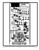
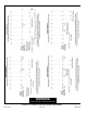
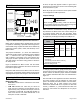
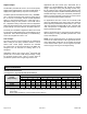
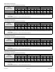
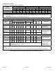
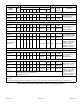
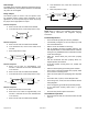
Table Of Contents
- BE5V Unit Dimensions – Upflow – Inches (mm)
- Shipping and Packing List
- General
- Requirements
- Installation Clearances
- Installation
- Condensate Drain
- Duct System and Filters
- Brazing Refrigerant Lines
- Sealing the Unit
- Electrical Connections
- BDC3 Blower Control
- Adjusting the Blower Speed
- Blower Performance
- Check-out Procedures
- Maintenance
- Repairing or Replacing Cabinet Insulation
- Professional Maintenance
- Use of Air Handler During Construction

507789-01B Issue 1818 Page 15 of 24
BDC3 Blower Control
JP1 15 PIN
PLUG (BOARD
TO MOTOR)
4
3
2
1
TEST
-
+
NORM
ADJUSTHEAT COOL DELAY CFM RUN
24V/1A
SERVICE
JP1
24V ACCESSORY
CONTACTS –
RATED FOR 1 AMP
OR LESS
OPERATIONAL
SELECTOR PINS
(AFFECTS BOTH
HEATING AND
COOLING MODES)
DIAGNOSTIC
LEDS
HEATING SPEED
SELECTOR PINS
COOLING SPEED
SELECTOR PINS
FAN DELAY
SELECTOR PINS
4
3
2
1
4
3
2
1
QC1
QC2
Figure 16. BDC3 Variable Speed Control Selections
BE5V units are equipped with a variable-speed motor that
is capable of maintaining a specied CFM throughout the
external static range. A particular CFM can be obtained by
positioning jumpers (COOL, HEAT, and ADJUST) on the
BDC3 control.
The jumpers are labeled 1, 2, 3, and 4. This indicates the
selected air volume (CFM). The ADJUST jumper is labeled
Test, -, +, and Norm. The - and + pin settings are used to
add or subtract a percentage of the CFM selected. The
Test jumper is used to operate the motor in the test mode.
The delay jumper controls the timing pattern in which the
fan delay occurs.
Figure 16 illustrates the BDC3 control. Use the blower
performance tables to determine the correct air volume for
heat and cool speed taps.
Diagnostic LEDs located on the BDC3 control to assist in
servicing the unit. Read the jumper settings section before
adjusting blower speed. Refer to Figure 16 for identication.
Adjusting the Blower Speed
Diagnostic LEDs
• RUN LED indicates there is a demand for the blower
motor to run.
• CFM LED indicates the cubic feet per minute at
which the unit is operating. The light ashes once for
approximately every 100 CFM. For example, if the unit
is operating at 1000 CFM, the CFM LED will ash 10
times. If the CFM is 1150, CFM LED will ash 11 full
times plus one fast or half ash.
At times, the light may appear to icker or glow. This is
normal and occurs when the control is communicating with
the motor between cycles.
Move the jumper pins to select the blower speed needed
to meet application CFM requirements.
Jumper Settings
Before changing jumper setting, make sure the motor
has completely stopped. Any jumper setting change will
not take place while the motor is running.
IMPORTANT
Table 2 lists the recommended factory blower speed
tap selections for BE5V series units. These settings are
for nominal tonnage match-ups with the BE5V. When
matched with other sizes, it is recommended that the CFM
be adjusted to provide approximately 400 CFM per ton.
Model
Speed Tap Selection
Cooling Heating*
Note 1 Note 2 Note 3 Note 4
BE5V24MA4X
COOL
PIN #3
COOL
PIN #3
HEAT
PIN #3
HEAT
PIN #3
BE5V30MA4X
BE5V36MA4X
BE5V42MA4X
BE5V48MA4X
BE5V60MA4X
NOTES -
1. Condensing Unit
2. Heat Pump
3. Condensing Unit with electric heat only
4. Heat Pump with electric heat
* Minimum setting for heat
Table 2. Recommended Blower Speed Taps
To change jumper positions, gently pull the jumper off the
pins and insert it onto the desired set of pins. The following
section outlines the different jumper selections available
and conditions associated with each one as illustrated in
Figure 16.
After the CFM for each application has been determined,
the jumper settings must be adjusted to reect those
given in the blower performance tables. From the tables,
determine which row of CFM volumes most closely
matches the desired CFM. Once a specic row has been
chosen (+, NORMAL, or -), CFM volumes from other rows
cannot be used. Below are descriptions of the jumper
selections.