
BE5V Installation Instructions
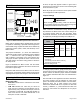
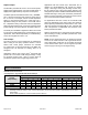
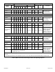
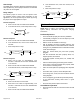
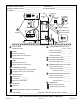
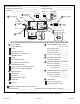
Table Of Contents
- BE5V Unit Dimensions – Upflow – Inches (mm)
- Shipping and Packing List
- General
- Requirements
- Installation Clearances
- Installation
- Condensate Drain
- Duct System and Filters
- Brazing Refrigerant Lines
- Sealing the Unit
- Electrical Connections
- BDC3 Blower Control
- Adjusting the Blower Speed
- Blower Performance
- Check-out Procedures
- Maintenance
- Repairing or Replacing Cabinet Insulation
- Professional Maintenance
- Use of Air Handler During Construction

507789-01B Issue 1818 Page 21 of 24
Check Cooling Operation
1. Set thermostat to force a call for cooling (approximately
5ºF lower than the indoor ambient temperature).
2. The outdoor unit should come on immediately and the
indoor blower should start between 30 - 60 seconds
later.
3. Check the air ow from a register to conrm that the
system is moving cooled air.
4. Set the thermostat 5ºF higher than the indoor
temperature. The indoor blower and outdoor unit
should cycle off.
Check Electric Heat (If Used)
1. Set thermostat to call for auxiliary heat (approximately
5°F above ambient temperature). The indoor blower
and auxiliary heat should come on together. Allow a
minimum of 3 minutes for all sequencers to cycle on.
2. Set the thermostat so that it does not call for heat.
Allow up to 5 minutes for all sequencers to cycle off.
Maintenance
Do not operate system without a lter. A lter is required
to protect the coil, blower, and internal parts from
excessive dirt and dust. The lter is placed in the return
duct by the installer.
IMPORTANT
Inspect air lters at least once a month and replace or
clean as required. Dirty lters are the most common cause
of inadequate heating or cooling performance.
Replace disposable lters. Cleanable lters can be cleaned
by soaking in mild detergent and rinsing with cold water.
Install new/clean lters with the arrows on the side pointing
in the direction of air ow. Do not replace a cleanable (high
velocity) lter with a disposable (low velocity) lter unless
return air system is properly sized for it.
If water should start coming from the secondary drain
line, a problem exists which should be investigated and
corrected. Contact a qualied service technician.
Repairing or Replacing Cabinet Insulation
DAMAGED INSULATION MUST BE REPAIRED OR
REPLACED before the unit is put back into operation.
Insulation loses its insulating value when wet, damaged,
separated or torn.
IMPORTANT
Matte- or foil-faced insulation is installed in indoor
equipment to provide a barrier between outside air
conditions (surrounding ambient temperature and humidity)
and the varying conditions inside the unit. If the insulation
barrier is damaged (wet, ripped, torn or separated from the
cabinet walls), the surrounding ambient air will affect the
inside surface temperature of the cabinet.
The temperature/humidity difference between the inside
and outside of the cabinet can cause condensation on the
inside or outside of the cabinet which leads to sheet metal
corrosion and, subsequently, component failure.
Repairing Damaged Insulation
Areas of condensation on the cabinet surface are an
indication that the insulation is in need of repair.
If the insulation in need of repair is otherwise in good
condition, the insulation should be cut in an X pattern,
peeled open, glued with an appropriate all-purpose glue
and placed back against the cabinet surface, being careful
to not overly compress the insulation so the insulation can
retain its original thickness. If such repair is not possible,
replace the insulation. If using foil-faced insulation, any
cut, tear, or separations in the insulation surface must be
taped with a similar foil-faced tape.
1. CUT INSULATION IN X PATTERN
2. APPLY GLUE
3. PRESS GLUED TABS AGAINST CABINET
GLUE - Make sure there is
full coverage of glue on the
metal or insulation so there
are no areas where air
pockets may form which
can lead to sweating.
Figure 17. Recommended Blower Speed Taps