
BE5V Installation Instructions
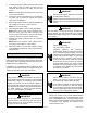
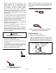
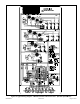
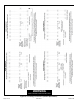
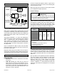
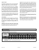
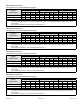
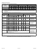
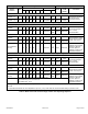
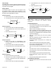
Table Of Contents
- BE5V Unit Dimensions – Upflow – Inches (mm)
- Shipping and Packing List
- General
- Requirements
- Installation Clearances
- Installation
- Condensate Drain
- Duct System and Filters
- Brazing Refrigerant Lines
- Sealing the Unit
- Electrical Connections
- BDC3 Blower Control
- Adjusting the Blower Speed
- Blower Performance
- Check-out Procedures
- Maintenance
- Repairing or Replacing Cabinet Insulation
- Professional Maintenance
- Use of Air Handler During Construction

507789-01B Issue 1818 Page 17 of 24
BE5V30 Blower Performance
0 through 0.80 in. w.g. External Static Pressure Range
ADJUST
Jumper Setting
Jumper Speed Positions
“HEAT” Speed First Stage “COOL” Speed Second Stage “COOL” Speed
1 2 3 4 1 2 3 4 1 2 3 4
cfm cfm cfm cfm cfm cfm cfm cfm cfm cfm cfm cfm
+ 680 885 1115 1340 490 635 770 930 680 885 1115 1340
NORM 620 810 1020 1220 440 575 715 845 620 810 1020 1220
– 550 725 905 1100 411 530 645 755 550 725 905 1100
NOTES - The effect of static pressure, lter and electric heater resistance is included in the air volumes listed.
First stage cooling air volume is 70% of COOL speed setting. Continuous blower speed is approximately 50% of COOL
speed setting.
Zoning System applications - minimum blower speed is 250 cfm.
BE5V36 Blower Performance
0 through 0.80 in. w.g. External Static Pressure Range
ADJUST
Jumper Setting
Jumper Speed Positions
“HEAT” Speed First Stage “COOL” Speed Second Stage “COOL” Speed
1 2 3 4 1 2 3 4 1 2 3 4
cfm cfm cfm cfm cfm cfm cfm cfm cfm cfm cfm cfm
+ 930 1155 1390 1530 640 815 970 1150 930 1155 1390 1530
NORM 830 1050 1260 1450 590 725 875 1025 830 1050 1260 1450
– 740 940 1135 1330 545 650 780 910 740 940 1135 1330
NOTES - The effect of static pressure, lter and electric heater resistance is included in the air volumes listed.
First stage cooling air volume is 70% of COOL speed setting. Continuous blower speed is approximately 50% of COOL
speed setting.
Zoning System applications - minimum blower speed is 250 cfm.
BE5V42 Blower Performance
0 through 0.80 in. w.g. External Static Pressure Range
ADJUST
Jumper Setting
Jumper Speed Positions
“HEAT” Speed First Stage “COOL” Speed Second Stage “COOL” Speed
1 2 3 4 1 2 3 4 1 2 3 4
cfm cfm cfm cfm cfm cfm cfm cfm cfm cfm cfm cfm
+ 1130 945 1575 1810 780 945 1110 1275 1130 945 1575 1810
NORM 1020 1255 1440 1650 710 860 1000 1160 1020 1255 1440 1650
– 920 1135 1300 1490 670 780 910 1040 920 1135 1300 1490
NOTES - The effect of static pressure, lter and electric heater resistance is included in the air volumes listed.
First stage cooling air volume is 70% of COOL speed setting. Continuous blower speed is approximately 50% of COOL
speed setting.
Zoning System applications - minimum blower speed is 450 cfm.
BE5V48 Blower Performance
0 through 0.80 in. w.g. External Static Pressure Range
ADJUST
Jumper Setting
Jumper Speed Positions
“HEAT” Speed First Stage “COOL” Speed Second Stage “COOL” Speed
1 2 3 4 1 2 3 4 1 2 3 4
cfm cfm cfm cfm cfm cfm cfm cfm cfm cfm cfm cfm
+ 1375 1600 1820 2185 960 1125 1285 1620 1375 1600 1820 2185
NORM 1260 1455 1655 2085 885 1035 1185 1475 1260 1455 1655 2085
– 1125 1310 1490 1885 790 925 1060 1330 1125 1310 1490 1885
NOTES - The effect of static pressure, lter and electric heater resistance is included in the air volumes listed.
First stage cooling air volume is 70% of COOL speed setting. Continuous blower speed is approximately 50% of COOL
speed setting.
Zoning System applications - minimum blower speed is 450 cfm.