
BE5C Installation Instructions
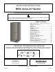
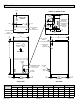
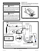
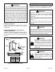
Table Of Contents
- BE5C Unit Dimensions – Upflow – Inches (mm)
- Shipping and Packing List
- General
- Requirements
- Installation Clearances
- Installation
- Condensate Drain
- Duct System and Filters
- Brazing Refrigerant Lines
- Sealing the Unit
- Electrical Connections
- Air Flow – Cooling Blower Speed
- Check-Out Procedures
- Operation
- Homeowner Maintenance
- Repairing or Replacing Cabinet Insulation
- Professional Maintenance
- Use of Air Handler During Construction

507787-01B Issue 1913 Page 9 of 22
If a high efciency lter is being installed as part of this
system to ensure better indoor air quality, the lter must
be properly sized. High efciency lters have a higher
static pressure drop than standard efciency glass/foam
lters. If the pressure drop is too great, system capacity
and performance may be reduced. The pressure drop
may also cause the limit to trip more frequently during
the winter and the indoor coil to freeze in the summer,
resulting in an increase in the number of service
calls. Before using any lter with this system, check
the specications provided by the lter manufacturer
against the data given in the appropriate Product
Specications. Additional information is provided in
Service and Application Note ACC002 (August 2000).
IMPORTANT
Installing Duct System
Connect supply air duct to the ange on top of the air
handler. If an isolation connector is used, it must be
nonammable.
Field-Fabricated Return Air Duct Flange for
Horizontal Applications
A return air duct system is recommended, but not factory-
provided. If the unit is installed in a conned space or
closet, run a full-size return connection to a location outside
the closet.
BOTTOM OF
CABINET
DUCT
ADAPTER
1−1/2
(38)
”A”
BRAKE DOWN 90 DEGREES
1/4 (6) DIA.
2−HOLES
"A"
1−1/2(38)
3/4
(19)
3/4
(19)
1−1/2
(38)
3/4
(19)
1/2
(13)
3/4
(19)
DUCT
FLANGE
CABINET
DOOR FLANGE
UNIT SIZE
Cabinet and Duct Flange
-018, -024,
-030
-036, -042,
-048, -060
18-3/8"
21-1/2"
Figure 9. Cabinet and Duct Flange
Brazing Refrigerant Lines
Refrigerant lines must be connected by a qualied
technician in accordance with established procedures.
Refrigerant lines must be clean, dry, refrigerant-grade
copper lines. Air handler coils should be installed
only with specied line sizes for approved system
combinations.
Handle the refrigerant lines gently during the installation
process. Sharp bends or kinks in the lines will cause a
restriction.
Do not remove the caps from the lines or system
connection points until connections are ready to be
completed.
IMPORTANT
Polyol ester (POE) oils used with HFC-410A refrigerant
absorb moisture very quickly. It is very important that the
refrigerant system be kept closed as much as possible.
DO NOT remove line set caps or service valve stub
caps until you are ready to make connections.
WARNING
Danger of re. Bleeding the refrigerant
charge from only the high side may result in
pressurization of the low side shell and
suction tubing. Application of a brazing torch
to a pressurized system may result in
ignition of the refrigerant and oil mixture.
Check the high and low pressures before
applying heat.
WARNING
When using a high pressure gas such as
nitrogen to pressurize a refrigeration or air
conditioning system, use a regulator that
can control the pressure down to 1 or 2 psig
(6.9 to 13.8 kPa).
WARNING