
BE5C Installation Instructions
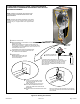
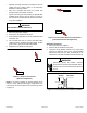
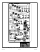
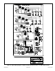

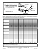
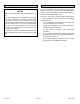
Table Of Contents
- BE5C Unit Dimensions – Upflow – Inches (mm)
- Shipping and Packing List
- General
- Requirements
- Installation Clearances
- Installation
- Condensate Drain
- Duct System and Filters
- Brazing Refrigerant Lines
- Sealing the Unit
- Electrical Connections
- Air Flow – Cooling Blower Speed
- Check-Out Procedures
- Operation
- Homeowner Maintenance
- Repairing or Replacing Cabinet Insulation
- Professional Maintenance
- Use of Air Handler During Construction

507787-01BIssue 1913Page 16 of 22
R
G
AIR
CONDITIONER
UNIT
R
R
G
G
BU
W
W
BK
COOLING‐ONLY APPLICATION
AIR HANDLERTHERMOSTAT
HEAT‐ONLY APPLICATION
AIR HANDLERTHERMOSTAT
COOLING APPLICATION WITH
ELECTRIC HEAT
AIR HANDLERTHERMOSTAT
HEAT PUMP APPLICATION WITH
ELECTRIC HEAT
NOTE - Connect common wire only if required (Refer to the appropriate thermostat installation instructions).
BU
BU
SEE
NOTE
SEE
NOTE
SEE
NOTE
Y
Y
AIR CONDITIONER
UNIT
R
G
BU
W
BK
CONNECT COMMON
WIRE ONLY IF
REQUIRED
(REFER TO THE
APPROPRIATE
THERMOSTAT
INSTALLATION
INSTRUCTIONS)
AIR HANDLER
THERMOSTAT
HEAT PUMP
UNIT
Figure 16. Low Voltage Connections (3-Speed PSC Motor) – Field Wiring
Air Flow – Cooling Blower Speed
The cooling blower speed is factory congured to provide
correct air ow for an outdoor unit that matches the cooling
capacity rating of the air handler.
If the outdoor unit is smaller than the maximum cooling
capacity rating for the air handler, the cooling blower speed
may need to be changed. Refer to blower performance
chart in Table 2.
Electric shock hazard! - Disconnect all power
supplies before servicing.
Replace all parts and panels before operating.
Failure to do so can result in death or electrical
shock.
WARNING
Change Blower Speed
1. Disconnect all power supplies.
2. Remove the air handler access panel.
3. Locate pin number 2 on the blower relay. Two black
wires are connected to this terminal pin. One connects
to pin number 5 on the blower relay, one connects to
an in-line splice connecting to a blue wire.
4. Select the required blower motor speed. Connect red-
LO or black-HI and plug it into the 4-pin blower relay
harness connector.
NOTE: Reuse the factory-installed wire nut on the
unused wires.
5. Replace all panels.
6. Reconnect power.