
BE5C Installation Instructions
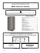
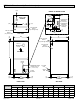
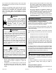
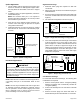
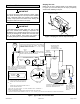
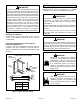
Table Of Contents
- BE5C Unit Dimensions – Upflow – Inches (mm)
- Shipping and Packing List
- General
- Requirements
- Installation Clearances
- Installation
- Condensate Drain
- Duct System and Filters
- Brazing Refrigerant Lines
- Sealing the Unit
- Electrical Connections
- Air Flow – Cooling Blower Speed
- Check-Out Procedures
- Operation
- Homeowner Maintenance
- Repairing or Replacing Cabinet Insulation
- Professional Maintenance
- Use of Air Handler During Construction

507787-01BIssue 1913Page 8 of 22
Install Condensate Drain
The air handler is provided with 3/4” NPT condensate drain
connections.
On some pans, the primary and secondary drain holes
have knockouts.
Conrm primary and secondary drains are open.
IMPORTANT
1. BE5C units are equipped with a drain pan, which
includes green (main drain) and red (secondary drain)
plugs. Unscrew the plugs to remove them before
inserting condensate drain ttings.
DRAIN PAN
RED SECONDARY
DRAIN PLUG
UNSCREW PLUGS
AND CONNECT
PROPERLY SIZED
FIELD-PROVIDED
FITTINGS AND
DRAIN LINES.
GREEN MAIN
DRAIN PLUG
Figure 8. Drain Line Connections
2. Install properly sized, eld-provided connection ttings
and connect primary drain line to the main drain pan
connection.
NOTE: When installing drain line connection ttings
to the drain pan, hand tighten the tting and use a
thread sealant. Over-tightening the ttings can split
connections on the drain pan.
3. If the secondary drain line is to be used, remove the
plug or the knockout and route the drain line so that
water draining from the outlet will be easily noticed
by the homeowner. Refer to local codes for drain trap
requirements on the secondary drain line.
4. Check again to ensure drain ports and drain pan are
free of all debris.
5. Plug and check any unused drain pan openings for
tightness. Torque plugs to 30 in. lb. to prevent water
leaks or seepage from the drain pan.
6. Install a 2” trap in the main (primary) drain lines as
close to the unit as practical (see Figure 7). Make sure
the top of the trap is below the connection to the drain
pan to allow complete drainage of the pan.
NOTE: Horizontal runs must have an anti-siphon air
vent (standpipe) installed ahead of the horizontal run.
See Figure 7. An extremely long horizontal run may
require an oversized drain line to eliminate air traps.
NOTE: Do not operate air handler without a trap in
the main (primary) drain. The condensate drain is on
the negative pressure side of the blower; therefore, air
being pulled through the condensate line will not allow
positive drainage without a proper trap.
7. Route the drain line to the outside or to an appropriate
drain. Drain lines must be installed so they do not block
service access to the front of the air handler. A 24”
clearance is required for lter, coil, or blower removal
and service access.
NOTE: Check local codes before connecting the drain line
to an existing drainage system. Insulate the drain lines
where sweating could cause water damage.
Test Condensate Drain
Test the drain pan and drain line after installation:
1. Pour several quarts of water into drain pan. Use
enough water to ll both the drain trap and the line.
2. Check the installed drain pan. Drain pan must be
draining completely. Drain line ttings must not be
leaking. Water must be draining from the end of the
primary drain line.
3. Correct any leaks found.
Duct System and Filters
Duct System
The air handler is provided with anges for the connection
of the supply plenum.
Supply and return duct system must be adequately sized
to meet the system’s air requirements and static pressure
capabilities. The duct system should be insulated with
a minimum of 1” thick insulation with a vapor barrier in
conditioned areas or 2” minimum in unconditioned areas.
Supply plenum should be the same size as the anged
opening provided around the blower outlet and should
extend at least 3 ft. from the air handler before turning or
branching off plenum into duct runs. The plenum forms
an extension of the blower housing and minimizes air
expansion losses from the blower.
Filters
A lter is provided. Table 1 lists the lter size for each unit.
BE5C Filter Size – in.
-018, -024, -030 15" x 20" x 1"
-036, -042, -048, -060 18" x 20" x 1"
Table 1. Unit Air Filter Size Chart