
BE5C Installation Instructions
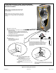
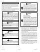
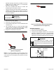
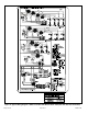
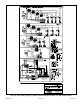
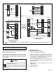
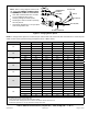
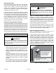
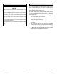
Table Of Contents
- BE5C Unit Dimensions – Upflow – Inches (mm)
- Shipping and Packing List
- General
- Requirements
- Installation Clearances
- Installation
- Condensate Drain
- Duct System and Filters
- Brazing Refrigerant Lines
- Sealing the Unit
- Electrical Connections
- Air Flow – Cooling Blower Speed
- Check-Out Procedures
- Operation
- Homeowner Maintenance
- Repairing or Replacing Cabinet Insulation
- Professional Maintenance
- Use of Air Handler During Construction

507787-01B Issue 1913 Page 13 of 22
• Separate openings have been provided for 24V low
voltage and line voltage. Refer to the dimension
illustration of specic location.
• This unit is provided with holes for conduit. Use
provided caps to seal holes not used.
• Typical unit wiring (as well as wiring of optional eld-
installed electric heat) is given in Figure 14. Refer to
the instructions provided with the electric heat section
for proper installation.
USE COPPER CONDUCTORS ONLY
WARNING
1. Disconnect all power supplies.
2. Remove the air handler access panel.
3. Route the eld supply wires to the air handler electrical
connection box.
4. Use UL-listed wire nuts to connect the eld supply
conductors to the unit black and yellow leads, and the
ground wire to ground terminal marked GND.
5. Replace the air handler access panel.
SIDE
TOP
Figure 11. Electrical Connections
(Upow Conguration)
NOTE: To avoid the possibility of moisture damage to the
control in some right-hand discharge congurations, the
control panel can be relocated to the end panel as shown
in Figure 12.
TOP
SIDE
Figure 12. Control Panel Relocated to End Panel
(Left-Hand Horizontal Conguration)
208 Volt Conversion
1. Disconnect all power supplies.
2. Remove the air handler access panel.
3. Using the wiring diagram located on the unit access
panel as a reference, move the 2 connected black
transformer leads from the 240 volt terminal on the
transformer to the 208 volt terminal on the transformer.
Electrically ground air handler. Connect
ground wire to ground terminal marked “GND”.
Failure to do so can result in death or electrical
shock.
WARNING
208 / 240 VOLT TRANSFORMER
PRIMARY SECONDARY
240 Volts
208 Volts
Figure 13. Converting Unit from 240VAC to 208VAC