
BG961UHE Gas Furnace Installation Manual
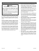
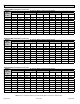
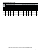
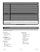
Table Of Contents
- Unit Dimensions
- Parts Arrangement
- Gas Furnace
- Shipping and Packing List
- Safety Information
- General
- Combustion, Dilution & Ventilation Air
- Installation
- Filters
- Duct System
- Venting Practices
- Condensate Piping
- Gas Piping
- Electrical
- Unit Start-Up
- Testing for Proper Venting and Sufficient Combustion Air for Non-Direct Vent Applications
- Other Unit Adjustments
- Blower Performance
- Service
- Planned Service
- Repair Parts List

507768-02B Page 55 of 56Issue 1904
Repair Parts List
The following repair parts are available through Blue Summit dealers. When ordering parts, include the complete furnace
model number listed on the CSA nameplate. All service must be performed by a licensed professional installer (or equivalent),
service agency, or gas supplier.
Cabinet Parts
• Upper Access Panel
• Blower Access Panel
• Top Cap
Control Panel Parts
• Transformer
• Integrated Control Board
• Door Interlock Switch
Blower Parts
• Blower Wheel
• Motor
• Motor Mounting Frame
• Motor Capacitor
• Blower Housing Cutoff Plate
Heating Parts
• Flame Sensor
• Heat Exchanger Assembly
• Gas Manifold
• Combustion Air Inducer
• Gas Valve
• Main Burner Cluster
• Main Burner Orices
• Pressure Switch
• Ignitor
• Primary Limit Control
• Flame Rollout Switches
Table 13. Diagnostic Codes
-03 Integrated Control LED Codes
Red LED Flash Code
2
Diagnostic Codes / Status of Furnace
LED Off No power to control or control hardware fault detected
Heartbeat
1
Normal operation - idle, continuous fan, cool
Continuous Rapid Flash Call for heat / burner operation
1 Flash Reverse line voltage polarity
2 Flashes Improper earth ground
3 Flashes Burner failed to light, or lost ame during heat demand
4 Flashes Low ame signal - check ame sensor
5 Flashes Watchguard - burner failed to light, exceeded maximum number of retries or recycles
6 Flashes Not used
7 Flashes Primary or Secondary limit open or watchguard mode - limit switch open longer than 3 minutes
8 Flashes Rollout switch open
9 Flashes Pressure switch failed to close or opened during heat demand
10 Flashes Watchguard - Pressure switch opened 5 times during one heat demand
11 Flashes Pressure switch stuck closed prior to activation of combustion air inducer
12 Flashes Flame sensed without gas valve energized
13 Flashes Low line voltage
1
A “heartbeat” is indicated by a “slow ash” - 1 sec on 1 sec off, repeating
2
Error codes are indicated by a “rapid ash” - the LED ashes X times at 1/2 sec on, 1/2 sec off, remains off for 3 sec, then repeats
NOTE: Last 10 error codes are stored in memory, including when power is shut off to the unit. To recall, press and release button.
Most recent will be displayed rst, LED off for 3 sec, then next error code is displayed, etc. To clear error codes, depress and hold
button longer than 5 seconds.