
BG961UHE Gas Furnace Installation Manual
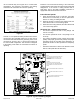
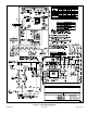
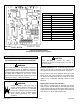
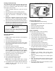
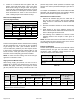
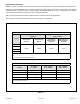
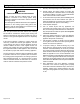
Table Of Contents
- Unit Dimensions
- Parts Arrangement
- Gas Furnace
- Shipping and Packing List
- Safety Information
- General
- Combustion, Dilution & Ventilation Air
- Installation
- Filters
- Duct System
- Venting Practices
- Condensate Piping
- Gas Piping
- Electrical
- Unit Start-Up
- Testing for Proper Venting and Sufficient Combustion Air for Non-Direct Vent Applications
- Other Unit Adjustments
- Blower Performance
- Service
- Planned Service
- Repair Parts List

507768-02BPage 42 of 56 Issue 1904
use an external relay. See Figure 68 for control board
conguration. This terminal is energized in the heating
mode when the combustion air inducer is operating.
Figure 65.
One 24V “H” 1/4” spade terminal is provided on the furnace
control board. Any humidier rated up to 0.5 amp can be
connected to this terminal with the ground leg of the circuit
connected to ground or the “C” terminal. See Figure 68
for control board conguration. This terminal is energized
in the heating mode when the combustion air inducer is
operating.
Install the room thermostat according to the instructions
provided with the thermostat. See Figure 65 for thermostat
designations. If the furnace is being matched with a
heat pump, refer to the FM21 installation instruction or
appropriate dual fuel thermostat instructions.
Indoor Blower Speeds
1. When the thermostat is set to “FAN ON”, the indoor
blower will run continuously on the fan speed when
there is no cooling or heating demand.
2. When the furnace is running in the heating mode, the
indoor blower will run on the heating speed.
3. When there is a cooling demand, the indoor blower will
run on the cooling speed.
Generator Use - Voltage Requirements
• The furnace requires 120 volts ± 10% (Range: 108
volts to 132 volts)
• The furnace operates at 60 Hz ± 5% (Range: 57 Hz
to 63 Hz)
• The furnace integrated control requires both proper
polarity and proper ground. Both polarity and proper
grounding should be checked before attempting to
operate the furnace on either permanent or temporary
power.
• Generator should have a wave form distortion of less
than 5% THD (total harmonic distortion).
Figure 66. Typical Field Wiring Diagram
NOTE-
IF ANY WIRE IN THIS APPLIANCE IS REPLACED,
IT MUST BE REPLACED WITH WIRE OF LIKE
SIZE, RATING, INSULATION THICKNESS AND
TERMINATION.
WARNING-
ELECTRIC SHOCK HAZARD. CAN CAUSE
INJURY OR DEATH. UNIT MUST BE GROUNDED
IN ACCORDANCE WITH NATIONAL AND LOCAL
CODES.
‘R’ IS REQUIRED ON SOME OUTDOOR UNITS
L13 POWER CHOKE USED ON 3/4 AND 1 HP
ONLY
S145 IS USED WITH HONEYWELL GAS VALVE
WHEN APPLIED IN LP GAS UNTIS