
BG961UHE Gas Furnace Installation Manual
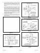
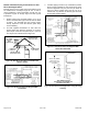
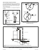
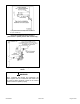
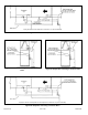
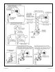
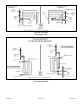
Table Of Contents
- Unit Dimensions
- Parts Arrangement
- Gas Furnace
- Shipping and Packing List
- Safety Information
- General
- Combustion, Dilution & Ventilation Air
- Installation
- Filters
- Duct System
- Venting Practices
- Condensate Piping
- Gas Piping
- Electrical
- Unit Start-Up
- Testing for Proper Venting and Sufficient Combustion Air for Non-Direct Vent Applications
- Other Unit Adjustments
- Blower Performance
- Service
- Planned Service
- Repair Parts List

507768-02B Page 35 of 56Issue 1904
Figure 53. Condensate Trap Locations
(Unit shown in upow position with remote trap)
* Piping from furnace must slope down a minimum of
1/4” per ft. toward trap.
Figure 54. Condensate Trap with Optional Overow
Switch
When combining the furnace and evaporator coil
drains together, the A/C condensate drain outlet must
be vented to relieve pressure in order for the furnace
pressure switch to operate properly.
WARNING