
BG961UHE Gas Furnace Installation Manual
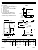
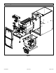
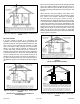
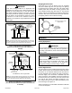
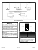
Table Of Contents
- Unit Dimensions
- Parts Arrangement
- Gas Furnace
- Shipping and Packing List
- Safety Information
- General
- Combustion, Dilution & Ventilation Air
- Installation
- Filters
- Duct System
- Venting Practices
- Condensate Piping
- Gas Piping
- Electrical
- Unit Start-Up
- Testing for Proper Venting and Sufficient Combustion Air for Non-Direct Vent Applications
- Other Unit Adjustments
- Blower Performance
- Service
- Planned Service
- Repair Parts List

507768-02BPage 2 of 56 Issue 1904
Front View
Top View
Side View
3/4
(19)
B
33
(838)
A
1
Bottom Return
Air Opening
9/16
(14)
Air Flow
C
3/4
(19)
14-3/4
(375)
16
(406)
2
Optional
Side Return
Air Filter Kit
(either side)
5/8
(16)
19-7/16 (494)
27-3/4 (705)
6-1/2 (165)
(either side)
14
(356)
Condensate
Trap Connection
(either side)
Electrical Inlet
(either side)
9 (229) Right
6-9/16 (167) Left
Gas Piping Inlet
(either side)
2 (51) (either side)
9/16
(14)
1 (25)
Front Panel
1
Bottom Return
Air Opening
3-1/4
(83)
12-5/8 (321)
(either side)
23
(584)
1
Side Return
Air Opening
(either side)
1-15/16 (49)
1-1/2
(38)
23-1/2 (597)
Supply Air
Opening
2 (51)
2-7/8
(73)
Exhaust Air
Outlet
Combustion
Air Intake
2
Optional
Side Return
Air Filter Kit
(either side)
23-3/4 (603)
25 (635)
3-3/8
(86)
D
1
NOTE - C*20 (5 Ton) size units installed in upow applications
that require air volumes of 1800 cfm (850 L/s) or greater must
have one of the following:
1. Single side return air with transition, to accommodate 20 x 25
x 1 in. (508 x 635 x 25 mm) cleanable air lter. (Required to
maintain proper air velocity.)
2. Single side return air with optional “RAB” Return Air Base.
3. Bottom return air.
4. Return air from both sides.
5. Bottom and one side return air.
See “Blower Performance Tables” for additional information.
2
Optional External Side Return Air Filter kit is not for use with
optional Return Air Base.
* Consider sizing requirements for optional IAQ equipment before
cutting side return opening.
Model
BG961UHE
A B C D
in. mm in. mm in. mm in. mm
045-12
070-12
17-1/2 446 16-3/8 416 16 406 7-5/8 194
090-16
110-20
21 533 19-7/8 505 19-1/2 495 9-3/8 238
Unit Dimensions