INSTALLATION INSTRUCTIONS BG961UHE Warm Air Gas Furnace Upflow/Horizontal Left and Right Air Discharge This manual must be left with the homeowner for future reference. This is a safety alert symbol and should never be ignored. When you see this symbol on labels or in manuals, be alert to the potential for personal injury or death. Table of Contents Unit Dimensions...........................................................2 Parts Arrangement.......................................................
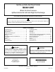
Unit Dimensions NOTE - C*20 (5 Ton) size units installed in upflow applications that require air volumes of 1800 cfm (850 L/s) or greater must have one of the following: 1 1. Top View Single side return air with transition, to accommodate 20 x 25 x 1 in. (508 x 635 x 25 mm) cleanable air filter. (Required to maintain proper air velocity.) 2. Single side return air with optional “RAB” Return Air Base. 3. Bottom return air. 4. Return air from both sides. 5. Bottom and one side return air.
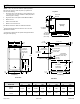
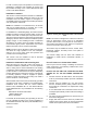
Parts Arrangement Figure 1.
Gas Furnace Shipping and Packing List The BG961UHE Category IV gas furnace is shipped ready for installation in the upflow or horizontal position. The furnace is shipped with the bottom panel in place. The bottom panel must be removed if the unit is to be installed in horizontal or upflow applications with bottom return air.
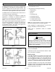
In order to ensure proper unit operation in non-direct vent applications, combustion and ventilation air supply must be provided according to the current National Fuel Gas Code or CSA-B149 standard. Installation Locations This furnace is CSA International certified for installation clearances to combustible material as listed on the unit nameplate and in the table in Figure 13 and Figure 18. Accessibility and service clearances must take precedence over fire protection clearances.
f. Return air temperature range between 60°F (16°C) and 80°F (27°C) must be maintained. g. MERV 11 or greater air filters must be installed in the system and must be regularly inspected and maintained (e.g., regular static checks and replaced at end of life) during construction. h. Blower and vestibule access panels must be in place on the furnace at all times. i.
the National Fuel Gas Code (ANSI-Z223.1/NFPA 54). This reprinted material is not the complete and official position of ANSI on the referenced subject, which is represented only by the standard in its entirety. WARNING Insufficient combustion air can cause headaches, nausea, dizziness or asphyxiation. It will also cause excess water in the heat exchanger resulting in rusting and premature heat exchanger failure.
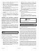
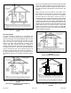
When communicating with the outdoors through horizontal ducts, each opening shall have a minimum free area of 1 square inch (645 mm²) per 2,000 Btu (.56 kW) per hour of the total input rating of all equipment in the enclosure. See Figure 8. Figure 5. Equipment in Confined Space - All Air From Inside When ducts are used, they shall be of the same crosssectional area as the free area of the openings to which they connect. The minimum dimension of rectangular air ducts shall be no less than 3 inches (75 mm).
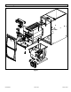
Shipping Bolt Removal WARNING If this unit is being installed in an application with combustion air coming in from a space serviced by an exhaust fan, power exhaust fan, or other device which may create a negative pressure in the space, take care when sizing the inlet air opening. The inlet air opening must be sized to accommodate the maximum volume of exhaust air as well as the maximum volume of combustion air required for all gas appliances serviced by this space.
Tilt the unit slightly (Max. 1/2”) from back to front to aid in the draining of the heat exchanger. Unit must be level side-to-side in all applications. Figure 12. Setting Equipment Top WARNING Improper installation of the furnace can result in personal injury or death. Combustion and flue products must never be allowed to enter the return air system or air in the living space. Use sheet metal screws and joint tape to seal return air system to furnace.
Return Air Guidelines Return air can be brought in through the bottom or either side of the furnace installed in an upflow application. If the furnace is installed on a platform with bottom return, make an airtight seal between the bottom of the furnace and the platform to ensure that the furnace operates properly and safely. The furnace is equipped with a removable bottom panel to facilitate installation.
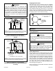
Right−Hand Discharge L e ft E n d R ight E nd Air Flow Air Flow Bottom (Floor)** Left−Hand Discharge Top L e ft E n d R ight E nd Air Flow Air Flow Bottom (Floor)** Figure 16. Removing the Bottom Panel Top/Plenum Top * Front Removing the Bottom Panel Remove the two screws that secure the bottom cap to the furnace. Pivot the bottom cap down to release the bottom panel. Once the bottom panel has been removed, reinstall the bottom cap. See Figure 16. Horizontal Applications 1 in.
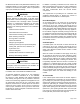
NOTE: Heavy-gauge sheet metal straps may be used to suspend the unit from roof rafters or ceiling joists. When straps are used to suspend the unit in this way, support must be provided for both the ends. The straps must not interfere with the plenum or exhaust piping installation. Cooling coils and supply and return air plenums must be supported separately. Filters This unit is not equipped with a filter or rack. A field provided filter is required for the unit to operate properly.
unit operates properly and safely. Use fiberglass sealing strips, caulking, or equivalent sealing method between the plenum and the furnace cabinet to ensure a tight seal. If a filter is installed, size the return air duct to fit the filter frame. the furnace, use ULC S636 approved One-Step Transition Cement to bond the pipe to the flue collar, or to bond the 90° elbow or reducing 90° elbow to the flue collar.
STANDARD Capacity VENT PIPE DIA. (in.) Outdoor Outdoor Exhaust Exhaust Accelerator Accelerator (Dia. X Length) (Dia.
NOTE: Assembly should be completed within 20 seconds after last application of cement. Hammer blows should not be used when inserting pipe. 8. After assembly, wipe excess cement from pipe at end of fitting socket. A properly made joint will show a bead around its entire perimeter. Any gaps may indicate an improper defective assembly due to insufficient solvent. 9. Handle joints carefully until completely set.
Vent Piping Guidelines REPLACING FURNACE THAT This gas furnace can be installed as either a Non-Direct Vent or a Direct Vent gas central furnace. WAS PART OF A COMMON VENT SYSTEM CHIMNEY OR GAS VENT (Check sizing for remaining appliance) NOTE: In non-Direct Vent installations, combustion air is taken from indoors and flue gases are discharged outdoors. In Direct Vent installations, combustion air is taken from outdoors and flue gases are discharged outdoors.
IMPORTANT Do not use screens or perforated metal in exhaust or intake terminations. Doing so will cause freeze-ups and may block the terminations. Capacity Min. Vent Length* 045, 070, 090, 110 15 ft or 5 ft plus 2 elbows or 10 ft plus 1 elbow 1 Furnace capacity? 045, 070, 090, 110 2 Which termination? Standard or Concentric? See Table 3 3 Which needs most elbows? Intake or Exhaust? 4 How many? 5 Desired pipe size? 6 What is the altitude? 7 Use Table 5 to find max pipe length.
BG961UHE Maximum Allowable Intake or Exhaust Vent Length in Feet Standard Termination at Elevation 0 - 4,500 ft 2-1/2" Pipe Capacity 2” Pipe Capacity 3" Pipe Capacity Number of 90° Elbows Used 045 070 090 110 045 070 090 110 045 070 090 110 1 76 61 39 19 110 95 63 38 132 132 113 113 2 3 4 5 6 7 8 9 10 71 66 61 56 51 46 41 36 31 56 51 46 41 36 31 26 21 16 34 29 24 19 14 9 14 9 105 90 58 33 127 100 85 53 28 122 95 80 48 23 117 90 75 43 18 112 85 70 38 13 107 80 65 33 8 102 n/
BG961UHE Maximum Allowable Intake or Exhaust Vent Length in Feet Concentric Termination at Elevation 0 - 4,500 ft 2-1/2" Pipe Capacity 2” Pipe Capacity 3" Pipe Capacity Number of 90° Elbows Used 045 070 090 110 045 070 090 110 045 070 090 110 1 68 53 37 17 100 85 59 34 116 116 109 109 2 3 4 5 6 7 8 9 10 63 58 53 48 43 38 33 28 23 48 43 38 33 28 23 18 13 8 32 27 22 17 12 7 12 7 95 80 54 29 111 90 75 49 24 106 85 70 44 19 101 80 65 39 14 96 75 60 34 91 70 55 29 86 n/a 65 50 2
Maximum Allowable Exhaust Vent Lengths with Furnace Installed in a Closet or Basement Using Ventilated Attic or Crawl Space for Intake Air in Feet Standard Termination at Elevation 0 - 4,500 ft 2-1/2" Pipe Capacity 2" Pipe Capacity Number of 90° Elbows Used 045 070 090 110 045 070 090 110 1 66 51 29 9 95 95 73 38 2 3 4 5 6 7 8 9 10 61 56 51 46 41 36 31 26 21 46 41 36 31 26 21 16 11 6 24 19 14 9 4 4 Number of 90° Elbows Used 045 3" Pipe Capacity 045 070 090 110 113 112 93 93
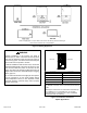
Figure 25. Figure 26.
Figure 27. Figure 28. Intake Piping 1. Use transition solvent cement or a sheet metal screw to secure the intake pipe to the inlet air connector. Figure 27 through Figure 28 This gas furnace may be installed in either direct vent or non-direct vent applications. In non-direct vent applications, when intake air will be drawn into the furnace from the surrounding space, the indoor air quality must be considered and guidelines listed in Combustion, Dilution and Ventilation Air section must be followed. 2.
intake opening (with the protective screen) should always be directed forward or to either side in the upflow position, and either straight out or downward in the horizontal position. The air intake piping must not terminate too close to the flooring or a platform. Ensure that the intake air inlet will not be obstructed by loose insulation or other items that may clog the debris screen. 2.
NOTE: See Table 6 for maximum allowed exhaust pipe length without insulation in unconditioned space during winter design temperatures below 32°F (0°C). If required exhaust pipe should be insulated with 1/2” (13 mm) Armaflex or equivalent. In extreme cold climate areas, 3/4” (19 mm) Armaflex or equivalent may be necessary. Insulation on outside runs of exhaust pipe must be painted or wrapped to protect insulation from deterioration. Exhaust pipe insulation may not be necessary in some specific applications.
Maximum Allowable Exhaust Vent Pipe Length (in ft.) without Insulation in Unconditioned Space For Winter Design Temperatures Single - Stage High Efficiency Furnace Winter Design Temperatures1 ºF (ºC) Unit Input Size Vent Pipe Diameter 045 PVC 32 to 21 (0 to -6) 20 to 1 (-7 to -17) 0 to -20 (-18 to -29) 070 2 PP PVC 090 2 PP PVC 110 2 PP PVC 2 PP 2 in. 18 16 31 28 50 48 30 30 2-1/2 in. 13 N/A 24 N/A 42 N/A 56 N/A 3 in. 9 9 18 18 35 35 47 47 2 in.
VENT TERMINATION CLEARANCES FOR NON-DIRECT VENT INSTALLATIONS IN THE US AND CANADA INSIDE CORNER DETAIL G H A D E B L Fixed Closed Operable F B B C Operable B K AREA WHERE TERMINAL IS NOT PERMITTED AIR SUPPLY INLET VENT TERMINAL M J A B I Fixed Closed US Installations1 A= Clearance above grade, veranda, porch, deck or balcony B= Clearance to window or door that may be opened C= Clearance to permanently closed window D= Vertical clearance to ventilated soffit located above the ter
VENT TERMINATION CLEARANCES FOR DIRECT VENT INSTALLATIONS IN THE USA AND CANADA INSIDE CORNER DETAIL G H A D E B L Fixed Closed Operable F B B C Operable B A B M K J AREA WHERE TERMINAL IS NOT PERMITTED AIR SUPPLY INLET VENT TERMINAL I Fixed Closed US Installations1 A= Clearance above grade, veranda, porch, deck or balcony B= Clearance to window or door that may be opened C= Clearance to permanently closed window D= Vertical clearance to ventilated soffit located above the terminal
Details of Intake and Exhaust Piping Terminations for Direct Vent Installations Inches (MM) NOTE: In Direct Vent installations, combustion air is taken from outdoors and flue gases are discharged to outdoors. 2. Intake and exhaust pipes should be placed as close together as possible at termination end (refer to illustrations). Minimum separation is 3” (76 mm) on roof terminations and 6” (152 mm) on sidewall terminations. 3.
FIELD FABRICATED WALL TERMINATION NOTE − FIELD−PROVIDED REDUCER MAY BE REQUIRED TO ADAPT LARGER VENT PIPE SIZE TO TERMINATION 2” (51mm) 3” (76mm) Vent Pipe Vent Pipe D D B C1 A B Intake Elbow C2 A STRAIGHT APPPLICATION * WALL SUPPORT D E D E B B A C1 EXTENDED APPLICATION A C2 A− Minimum clearance above grade or average snow accumulation 12” (305 mm) 12” (305 mm) B− Maximum horizontal separation between intake and exhaust 6” (152 mm) 6” (152 mm) C1 -Minimum from end of exhaust t
6. On field supplied terminations, a minimum distance between the end of the exhaust pipe and the end of the intake pipe without a termination elbow is 8” and a minimum distance of 6” with a termination elbow. See Figure 39. 7. If intake and exhaust piping must be run up a side wall to position above snow accumulation or other obstructions, piping must be supported every 24” (610 mm) as shown in Figure 39.
Details of Exhaust Piping Terminations for NonDirect Vent Applications 3. Exhaust pipes may be routed either horizontally through an outside wall or vertically through the roof. In attic or closet installations, vertical termination through the roof is preferred. Figure 45 through Figure 48 show typical terminations. 1. 2. If exhaust piping must be run up a sidewall to position above snow accumulation or other obstructions, piping must be supported every 24” (610 mm) as shown in Figure 47.
Exhaust through Crawl Space Vent Option All 33” condensing gas furnaces (92%+) are now approved to be vented down through a crawl space. Ensure a vent pipe drain kit, 51W18 (USA) or 15Z70 (Canada), is used as directed through the floor joists and into the crawl space. See the following figures. Exhaust from Furnace To Termination Consult the vent tables for vent lengths and approved materials.
5. Condensate Piping This unit is designed for either right or left side exit of condensate piping in upflow applications. In horizontal applications, the condensate trap must extend below the unit. An 8” service clearance is required for the condensate trap. Refer to Figure 52 for condensate trap locations. Figure 59 shows trap assembly using 1/2” PVC or 3/4” PVC. Figure 55 and Figure 56 show the furnace and evaporator coil using a separate drain.
* Piping from furnace must slope down a minimum of 1/4” per ft. toward trap. Figure 53. Condensate Trap Locations (Unit shown in upflow position with remote trap) Figure 54. Condensate Trap with Optional Overflow Switch WARNING When combining the furnace and evaporator coil drains together, the A/C condensate drain outlet must be vented to relieve pressure in order for the furnace pressure switch to operate properly.
* Piping from furnace must slope down a minimum of 1/4” per ft. toward trap. Figure 55. Condensate Trap Locations Figure 56. Unit with Cooling Coil Using Separate Drain Figure 57. Evaporator Coil Using a Common Drain Piping from furnace and evaporator coil must slope down a minimum 1/4” per ft. toward trap. Figure 58.
Figure 59.
Gas Piping IMPORTANT Compounds used on threaded joints of gas piping must be resistant to the actions of liquified petroleum gases. CAUTION If a flexible gas connector is required or allowed by the authority that has jurisdiction, black iron pipe shall be installed at the gas valve and extend outside the furnace cabinet. The flexible connector can then be added between the black iron pipe and the gas supply line.
Figure 61. Gas Piping Upflow Applications Figure 62.
Gas Pipe Capacity - FT³/HR (kL/HR) Nominal Iron Pipe Size inches (mm) Internal Diameter - inches (mm) Length of Pipe - feet (m) 10 20 30 (3.048) (6.096) (9.144) 40 50 60 70 80 90 100 (12.192) (15.240) (18.288) (21.336) (24.384) (27.432) (30.480) 1/2 .622 175 120 97 82 73 66 61 57 53 50 (12.7) (17.799) (4.96) (3.40) (2.75) (2.32) (2.07) (1.87) (1.73) (1.61) (1.50) (1.42) 3/4 .824 360 250 200 170 151 138 125 118 110 103 (19.05) (20.930) (10.19) (7.
The unit is equipped with a field makeup box. The makeup box may be moved to the right side of the furnace to facilitate installation. Seal unused openings on left side with plugs removed from right side. Secure the excess wire to the existing harness to protect it from damage. Electrical ELECTROSTATIC DISCHARGE (ESD) Precautions and Procedures Refer to Figure 66 for field wiring and Figure 67 for schematic wiring diagram and troubleshooting.
use an external relay. See Figure 68 for control board configuration. This terminal is energized in the heating mode when the combustion air inducer is operating. Install the room thermostat according to the instructions provided with the thermostat. See Figure 65 for thermostat designations. If the furnace is being matched with a heat pump, refer to the FM21 installation instruction or appropriate dual fuel thermostat instructions. Indoor Blower Speeds 1.
Figure 67.
Terminal Designations 120 HUM LINE Humidifier (120 VAC) Input (120 VAC) XFMR Transformer (120 VAC) CIRC Indoor Blower (120 VAC) EAC Electronic Air Cleaner (120 VAC) COOL Blower - Cooling Speed (24 VAC) HEAT Blower - Heating Speed (24 VAC) FAN PARK NEUTRALS FS Blower - Fan Speed (24 VAC) Dead terminals to park all speed taps Neutral Terminals (120 VAC) Flame Sense 24 COM Common (24 VAC) HUM 24 Humidifier (24 VAC) Figure 68.
Priming Condensate Trap The condensate trap should be primed with water prior to start-up to ensure proper condensate drainage. Either pour 10 fl. oz. (300 ml) of water into the trap, or follow these steps to prime the trap: 1. Follow the lighting instructions to place the unit into operation. 2. Set the thermostat to initiate a heating demand. 3. Allow the burners to fire for approximately 3 minutes. 4. Adjust the thermostat to deactivate the heating demand. 5.
6. pressure may result in erratic operation or underfire. High pressure can result in permanent damage to gas valve or overfire. If flame is not detected after first ignition trial, the ignition control will repeat steps 3 and 4 four more times before locking out the gas valve. The ignition control will then automatically repeat steps 1 through 6 after 60 minutes. To interrupt the 60 minute period, move thermostat from “Heat” to “OFF” then back to “Heat”. Heating sequence then restarts at step 1.
High Altitude Information NOTE: In Canada, certification for installations at elevations over 4500 feet (1371 m) is the jurisdiction of local authorities. Units may be installed at altitudes up to 10,000 ft. above sea level. See Table 11 for de-rate manifold values. Units installed at altitude of 7501 - 10,000 feet require an orifice change. Units installed at altitudes of 4,501 - 10,000 feet (1371 -3048 m) may require a pressure switch change which can be ordered separately.
Testing for Proper Venting and Sufficient Combustion Air for Non-Direct Vent Applications 1. Seal any unused openings in the venting system. 2. Failure to follow the steps outlined below for each appliance connected to the venting system being placed into operation could result in carbon monoxide poisoning or death. Visually inspect the venting system for proper size and horizontal pitch.
Constant Torque Motor Other Unit Adjustments Primary Limit The primary limit is located on the heating compartment vestibule panel. This limit is factory set and requires no adjustment. These units are equipped with a constant torque ECM motor. It has a DC motor coupled to an electronic control module both contained in the same motor housing. The motor is programmed to provide constant torque at each of the five selectable speeds. The motor has five speed taps. Each tap requires 24 volts to energize.
Blower Performance BG961UH045BE12 Performance (Less Filter) External Static Pressure in. w.c. Air Volume / Watts at Various Blower Speeds cfm Watts cfm Watts cfm Watts cfm Watts cfm Watts 0.00 1460 335 1285 235 1190 170 910 85 870 75 0.10 1430 350 1260 245 1155 185 885 95 830 85 0.20 1405 365 1235 255 1125 200 860 105 800 90 0.30 1375 370 1205 265 1090 210 825 115 755 95 0.40 1350 380 1175 275 1055 215 780 125 710 105 0.
BG961UH110CE20 Performance (Less Filter) Air Volume / Watts at Various Blower Speeds External Static Pressure in. w.c. Bottom Return Air, Side Return Air with Optional Return Air Base, Return Air from Both Sides or Return Air from Bottom and One Side. High Medium - High Medium Medium - Low Single Side Return Air - Air volumes in bold require field fabricated transition to accommodate 20 x 25 x 1 in. air filter in order to maintain proper air velocity.
Winterizing and Condensate Trap Care Service 1. Turn off power to the furnace. WARNING ELECTRICAL SHOCK, FIRE, OR EXPLOSION HAZARD. 2. Have a shallow pan ready to empty condensate water. 3. Remove the clean out cap from the condensate trap and empty water. Inspect the trap then reinstall the clean out cap. Cleaning Heat Exchanger Failure to follow safety warnings exactly could result in dangerous operation, serious injury, death or property damage.
19. Remove the primary limit from the vestibule panel. 41. Reconnect flame rollout switch wires. 20. Remove top cap screws to allow top cap to be tilted upward to allow clearance for removing heat exchanger. 42. Reconnect sensor wire and reconnect 2 pin plug from ignitor. 21. Remove two screws from the front cabinet flange at the blower deck. Spread cabinet sides slightly to allow clearance for removal of heat exchanger. 44. Replace the blower compartment access panel. 22.
Planned Service A service technician should check the following items during an annual inspection. Power to the unit must be shut off for safety. Fresh air grilles and louvers (on the unit and in the room where the furnace is installed) - Must be open and unobstructed to provide combustion air. Burners - Must be inspected for rust, dirt, or signs of water. Vent pipe - Must be inspected for signs of water, cracked, damaged or sagging pipe, or disconnected joints.
-03 Integrated Control LED Codes Red LED Flash Code Diagnostic Codes / Status of Furnace 2 LED Off Heartbeat No power to control or control hardware fault detected 1 Normal operation - idle, continuous fan, cool Continuous Rapid Flash Call for heat / burner operation 1 Flash Reverse line voltage polarity 2 Flashes Improper earth ground 3 Flashes Burner failed to light, or lost flame during heat demand 4 Flashes Low flame signal - check flame sensor 5 Flashes Watchguard - burner failed to ligh
Requirements for Commonwealth of Massachusetts Modifications to NFPA-54, Chapter 10 4. Revise NFPA-54 section 10.8.