Operators & Parts Manual MANUAL NO. 107999 REV.
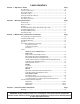
Lawn Aerators Section 1 · Operator’s Guide Page Specifications ................................................................................................. 3 Features and Controls ................................................................................. 4-6 General Information ........................................................................................ 7 Safety Procedures ..........................................................................................
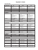
Operator’s Guide SPECIFICATIONS A) POWER UNIT Engine Clutch Primary drive Secondary drive Gear reduction B) WHEELS Bearings Rear tires Front tire C) AERATION Tines Aeration width Hole pattern Core depth Holes per sq ft Working speed Productivity D) WEIGHTS Net weight Shipping weight Removable weights E) DIMENSIONS Height Height overall Length Length overall Width Shipping carton 424 3.5HP Briggs I/C (2.6kw) 4HP Honda (3kw) Belt tensioner One V-belt (A-44”) Permalube Chain 6:1 530A 3.
Operator’s Guide MODEL 424 - FEATURES AND CONTROLS Figure 1 4
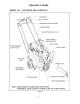
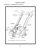
Operator’s Guide MODEL 530A - FEATURES AND CONTROLS Clutch Control Rear Wheel Control Handle Depth/Stability Control Knob Handle Stops Folding Handle Locking Cam Drive Guard Engine Guard Removable Weight Removable Weight Adjustable Rear Wheel Powered Front Wheel Note: Serial number is located on the rear of the housing.
Operator’s Guide MODEL 742 - FEATURES AND CONTROLS Figure 3 6
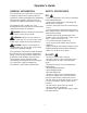
Operator’s Guide SAFETY PROCEDURES GENERAL INFORMATION This manual will assist you in the safe operation and proper maintenance of your Husqvarna equipment. Read it thoroughly before attempting to operate the machine. Call your dealer or Husqvarna if additional information is required. DO: • Read all maintenance and service instructions before attempting work. • Read engine manufacturer’s operating and maintenance instructions. • Remove spark plug wire before commencing service.
SAFETY AND INSTRUCTION DECALS The following decals are found on Model 424,530 and 742 aerators. If any are missing or not legible, replace them before operating aerator.
DECAL PLACEMENT - MODELS 424, 530A AND 742 G2 Throttle Cable (Model 742 with Honda only) G1 H (on deck behind engine) F (on back of housing over tine rotor) K (for Models 424 & 742 logo only) I J E (for Model 742) K D A (for Model 424) B (for Model 530A) C (for Model 742) Figure 3 9
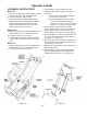
Operator’s Guide ASSEMBLY INSTRUCTIONS Model 424 1. Remove wooden blocks. Note: Watch for nails and wood splinters. Wear eye protection. 2. Carefully cut open side of carton. 3. Lawn Aerator 424 is shipped with handle folded. Rear wheel control handle strapped together with the clutch control. First cut straps, then unfold handle. Lock handle in position using the cam lock lever. Model 530A 1. Wear eye protection. Remove wooden blocks. NOTE: Watch for nails and wood splinters. 2.
Operating Instructions AERATION TIPS Should I water before aerating? Best aerating condition is a soft and moist ground. If you are unsure of the ground conditions, as in soil with high clay content, a simple test will determine whether it is necessary to water before aerating. Using a garden hand spade or a large screw driver, you should be able to drive the tool in the ground 2 to 3 inches with little effort. If you are unable to do so, then watering the lawn a day before aerating is necessary.
Operating Instructions THROTTLE CABLE ADJUSTMENT. Model 742 (Honda Engine Only) 1. Start engine and allow it to reach operating temperature. 2. Adjust the throttle cable at the adjuster bracket by turning the adjuster nut. Tightening will increase engine speed, loosening will reduce engine speed. NOTE: A properly adjusted throttle will slightly increase engine speed as the clutch engages. • If the clutch engages too soon, the engine will stall.
Operating Instructions NOTE: Adjusting for greater stability will shorten the length of the cores you pull. You will gain greater side-to-side stability (see below “Operating on Hills.” Adjustments for greater stability will also improve maneuverability during aeration.) OPERATING ON HILLS WARNING! DO NOT operate on hills exceeding 35% grade. TURNING AND MANEUVERING THE AERATOR Gradual maneuvering while aerating can be accomplished by simply guiding the machine.
Operating Instructions TRANSPORTING THE BLUEBIRD AERATOR When operating on hills you should consider the following: (A) Operate the machine up and down the hills rather than across them. (B) Use the rear wheel depth/stability control knob to set the rear wheels for extra stability. This can be a great benefit when you do choose to run the aerator across a hill.
Maintenance and Service Instructions CLEANING AND WASHING Regular cleaning, washing and lubricating will prolong the service of your machine. NOTE: Use care with power washers to avoid damage to Warning Decals, Operator Instruction Labels, Bearings,Chain and Engine. Limit direct spray on these items. DO NOT EXCEED 1000 PSI WATER PRESSURE FOR CLEANING TWO MINUTE WARNING STORAGE 1. Refer to engine manufacturers instructions for engine storage information. 2 Clean machine. 3.
Maintenance and Service Instructions TINE WEAR After your BlueBird Aerator has been used for sometime, the tines will wear. When this happens their aerating performance will diminish. Inspect tines using the drawing, replace when at minimum length or before. (Tines are 5” when new.) Drive Belt Replacement and Adjustment 1. Turn off engine and remove the drive guard cover. 2. Remove V-belt. 3. Inspect condition of V-pulleys and replace if necessary. 4.
Maintenance and Service Instructions Clutch Cable Removal and Replacement 1. Turn off engine and remove old clutch cable. 2. Route new cable through the hole at the rear of housing. 3. Attach clutch cable to the bracket on the spring on the idler assembly, then connect opposite end of cable to the S hook. 4. Adjust cable to obtain ¾” to1 ¼” extension of the clutch spring when clutch is engaged. (see Figure 12). 4. Attach the new adjuster bracket to the spring on the throttle/clutch lever.
Maintenance and Service Instructions Figure 14 Adjusting Chain Tension 1. Turn engine off. 2. Remove drive guard, loosen lock nut on idler adjustment bolt. 3. Turn idler adjustment bolt to adjust tension to allow 1/8" to 1/4" movement at the center point between the wheel sprocket and the rotor sprocket (see Figures 14 and 15). 4. Tighten lock nut. NOTE: BlueBird recommends the replacement of sprockets when replacing drive chain. HANDLE - MODEL 424 and 530A ONLY Inspection 1.
Maintenance and Service Instructions collar so that it rotates in the opposite direction the wheel would normally turn. If bearings are rusted in place they will have to be replaced along with the wheel and shaft. 8. Install bearings and sprocket loosely onto the shaft. Models 424 & 530A: hub side away from wheels. Model 742 has 3 bearings. Wheel bearings should have hubs facing away from wheel. Wheel shaft bearing should have hub facing away from sprocket. 9. Bolt bearings into place. 10.
Maintenance and Service Instructions 8. Remove the tine rotor shaft bearing bolts (4). 9. Remove chain scaper bolts (2) and chain scraper (on Model 424 only). 10. Remove the rotor shaft assembly. 11. Remove outer rotor bearing by loosening the set screw in the collar. Figure 17 12. Unlock collar (best accomplished by using a hammer and pin punch).
Parts Main Frame - Model 424 ITEM PART NO. 1 ...... 7144 2 ...... 7154 3 ...... 7186 4 ...... 7200 5 ...... 7201 6 ...... 7202 7 ...... 7203 9 ...... 0729 .......... 7227 QTY. DESCRIPTION .................2 ........... WEIGHT, 36 LBS., SOLID STEEL .................1 ........... HOUSING W/DECALS .................1 ........... DRIVE GUARD W/DECALS .................1 ........... DRIVE GUARD FASTENER KIT .................2 ........... LATCK KIT, WEIGHT W/HARDWARE .................1 ...........
Parts Handle and Control - Model 424 9 1 8 11 2 4 10 6 5 15 14 7 3 12 13 ITEM PART NO. QTY. DESCRIPTION 1 ...... 0034 .................2 ........... GRIP, CLUTCH 2 ...... 5129 .................1 ........... SPRING, CLUTCH 3 ...... 5256 .................1 ........... CAM, LOCKING 4 ...... 7149 .................1 ........... CLUTCH CONTROL W/GRIPS 5 ...... 7151 .................1 ........... HANDLE W/GRIPS 6 ...... 7174 .................1 ........... HANDLE, CONTROL, REAR WHEEL 7 ...... 7189 ....
Parts Rear Wheel - Model 424 ITEM PART NO. QTY. DESCRIPTION 1 ...... 0048 .................2 ........... BEARING, ROLLER W/BUSHING & SEALS 2 ...... 7107 .................2 ........... LIFT LINK 3 ...... 7133 .................1 ........... TORQUE ARM, DEPTH ADJUSTMENT 4 ...... 7148 .................1 ........... WHEEL CARRIAGE, AXLE 5 ...... 7163 .................1 ........... KNOB, DEPTH/STABILITY 6 ...... 7195 .................2 ........... SPRING, AXLE 7 ...... 7213 .................1 ...........
Parts Power Train & Tine Rotor - Model 424 24
Parts Power Train & Tine Rotor - Model 424 ITEM PART NO. QTY. DESCRIPTION 1 ...... 0301 .................1 ........... SPROCKET, JACKSHAFT, W/KEY & SPACER 2 ...... 0302 .................1 ........... SPROCKET, WHEEL, W/SET SCREWS & KEY 3 ...... 0303 .................1 ........... SPROCKET, ROTOR, W/SET SCREWS & KEY 4 ...... 0307 .................1 ........... MASTER LINK FOR 0308 5 ...... 0308 .................1 ........... CHAIN, #40 PERMA LUBE ROLLER 6 ...... 0315 .................4 ...........
Parts Main Frame - Model 530A 26
Parts Main Frame - Model 530A ITEM PART NO. 1 ...... 7600 2 ...... 7601 3 ...... 7602 4 ...... 7200 6 ...... 0729 .......... 7603 QTY. DESCRIPTION .................2 ........... .................1 ........... .................1 ........... .................1 ........... ............................... .................1 ........... WEIGHT, 36 LBS., SOLID STEEL HOUSING W/DECALS DRIVE GUARD W/DECALS DRIVE GUARD FASTENER KIT PAINT, BLUE, 1 QT.
Parts Handle & Control - Model 530A 1 2 6 14 15 6 23 6 9 7 12 19 11 5 4 15 20 3 8 15 22 21 10 6 16 20 15 17 6 18 24 28 13
Parts Handle & Control - Model 530A ITEM PART NO. QTY. DESCRIPTION 1 ...... 0033 .................2 ........... GRIPS, PAIR 2 ...... 990209 ..............2 ........... SCREW, 5/16-18 X 1 3 ...... 990184 ..............2 ........... NUT, 5/16-18 4 ...... 109303 ..............2 ........... RING, RETAINING 5 ...... 03895................2 ........... PIN, CLEVIS, 5/16 X 1.174 6 ...... 990188 ..............9 ........... WASHER, 5/16 7 ...... 108741 ..............2 ........... NUT, 10-32, FLANGE LOCK 8 ......
Parts Rear Wheel - Model 530A 30
Parts Rear Wheel - Model 530A ITEM PART NO. QTY. DESCRIPTION 1 ...... 0048 .................2 ........... BEARING, ROLLER W/BUSHING & SEALS 2 ...... 7107 .................2 ........... LIFT LINK 3 ...... 200219 ..............1 ........... TORQUE ARM, DEPTH ADJUSTMENT 4 ...... 7620 .................1 ........... WHEEL CARRIAGE, AXLE 5 ...... 7163 .................1 ........... KNOB, DEPTH/STABILITY 6 ...... 7195 .................2 ........... SPRING, AXLE 7 ...... 7213 .................1 ...........
Parts Power Train & Tine Rotor - Model 530A 32
Parts Power Train & Tine Rotor - Model 530A ITEM PART NO. QTY. DESCRIPTION 1 ...... 7630 .................1 ........... SPROCKET, JACKSHAFT, W/KEY & SPACER 2 ...... 0302 .................1 ........... SPROCKET, WHEEL, W/SET SCREWS & KEY 3 ...... 0303 .................1 ........... SPROCKET, ROTOR, W/SET SCREWS & KEY 4 ...... 0307 .................1 ........... MASTER LINK FOR 0308 5 ...... 0308 .................1 ........... CHAIN, #40 PERMA LUBE ROLLER 6 ...... 0315 .................4 ...........
Parts Main Frame - Model 742 ITEM PART NO. 1 ...... 7600 2 ...... 7400 3 ...... 7401 4 ...... 7200 5 ...... 7402 6 ...... 7203 7 ...... 7403 9 ...... 0729 .......... 7404 QTY. DESCRIPTION .................2 ........... WEIGHT, 36 LBS., SOLID STEEL, REMOVABLE .................1 ........... HOUSING W/DECALS .................1 ........... DRIVE GUARD W/DECALS .................1 ........... FASTENER KIT, DRIVE GUARD .................2 ........... FASTENER KIT, WEIGHT .................1 ...........
Parts Handle & Control - Model 742 ITEM PART NO. QTY. DESCRIPTION 1 ...... 0034 .................2 ........... GRIP, CLUTCH, 1 EACH 2 ...... 5129 .................1 ........... SPRING, CLUTCH 3 ...... 7149 .................1 ........... CLUTCH CONTROL, W/GRIPS .......... 7405 .................1 ........... CLUTCH/THROTTLE CONTROL ................................................... HONDA ENGINE ONLY 4 ...... 7406 .................1 ........... HANDLE W/GRIPS 5 ...... 7174 .................1 ...........
Parts Rear Wheel - Model 742 36
Parts Rear Wheel - Model 742 ITEM PART NO. QTY. DESCRIPTION 1 ...... 7409 .................2 ........... BEARING, ROLLER W/SEALS 2 ...... 7107 .................2 ........... LIFT LINK 3 ...... 7119 ..................1 ........... TORQUE ARM, DEPTH ADJUSTMENT 4 ...... 7410 .................2 ........... AXLE KIT: AXLE, E-CLIP, 2 WASHERS, ................................................... COTTER PIN, HAIRPIN COTTER 5 ...... 7163 .................1 ........... KNOB, DEPTH/STABILITY 6 ...... 7195 .........
Parts Power Train & Tine Rotor - Model 742 38
Parts Power Train & Tine Rotor - Model 742 ITEM PART NO. QTY. DESCRIPTION 1 ...... 7416 ................. 1 ........... SPROCKET, JACKSHAFT, W/KEY 2 ...... 7417 ................. 1 ........... SPROCKET, WHEEL W/SET SCREWS & KEY 3 ...... 7418 ................. 1 ........... SPROCKET, ROTOR, W/SET SCREWS & KEY 4 ...... 7419 ................. 1 ........... MASTER LINK FOR 7420 5 ...... 7420 ................. 1 ........... CHAIN, #50 PERMA LUBE ROLLER 6 ...... 0315 ................. 3 ...........
One Year Limited Warranty For one year from purchase, BlueBird will replace for the original purchaser, free of charge, any part or parts, found upon examination by any Factory Authorized Service Center, or by the Factory at Beatrice, Nebraska, to be defective in material or workmanship or both. All transportation charges on parts submitted for replacement under this warranty must be paid by purchaser. THERE IS NO OTHER WARRANTY EXPRESSED OR IMPLIED.