
Instructions / Assembly
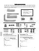
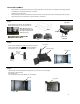
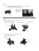
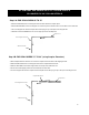
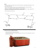
Table Of Contents
(2) Cover Support Arms 37” x 20”
Tools required for assembly:
1. Phillips Screwdriver
2. Power drill with a 1/16” drill bit
and a 1/4” drill bit.
3. Pen, Pencil or Marker
4. Wrench – ¾”
BEFORE YOU GET STARTED
You will need to make sure you have at least 2 feet of clearance of all 4 sides of your spa.
We reco mmend the coverlift opens towa rd the back of the spa away fro m the contro l panel. Mounting the
coverlift in an y othe r o rientation may cause interference w ith the spa's front acces s pan el if any repairs or
maintenance of spa is required in the future.
(2) Mounting Brackets
(2) Pivot Stopper Bolts
3 ¼” L, with rubber padding
(4) Spacer Block
(6) Washers
(4) 13/16” dia. & (2) 7/8” dia.
(4) Nuts
(18) 1” Self
Tapping Screws
(2) Pivot Arm Bolts 3 ½” L
-2 -
(30) Screw End Caps 7/16”
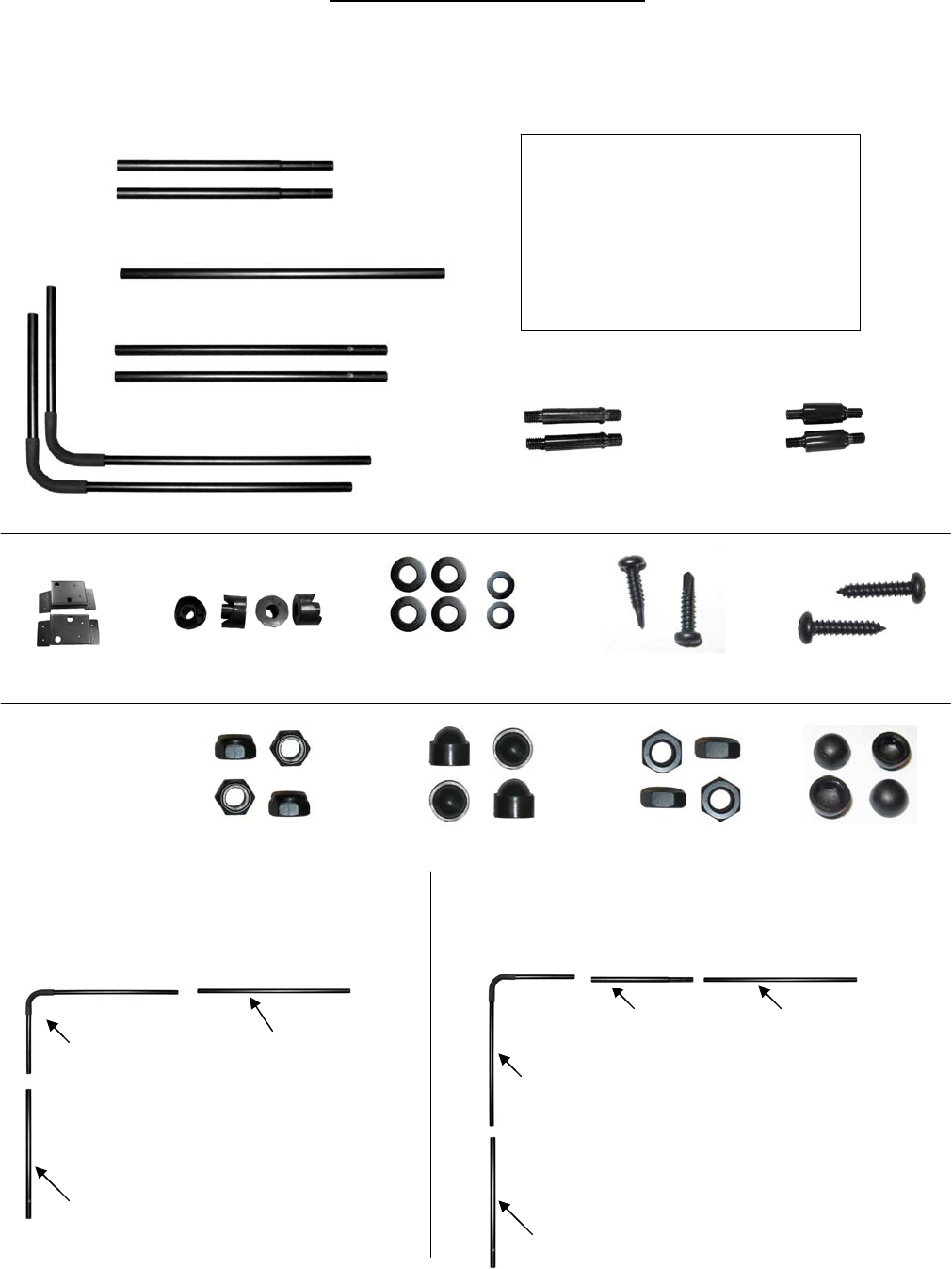
SPA COVERS UP TO 72
SPA COVERS UP TO 72
”
”
(do not use coupler
(do not u
se coupler
extension(s
exte
nsion(s
); position Cover Support
); posit
ion Cover Support
Arms so that the long end is on the top side of the cover)
Arms
so that the long end is on the top side of the cover)
SPA COVERS 73
SPA COVERS 73
”
”
-
-
96
96
”
”
(using coupler extension(s); position Cover Support Arms
so that the short end is on the top side of the cover)
(8) 1” Mounting Screws
(4) Locknut caps
(4) Locknuts
(2) Side Pivot Arm 32”
(2) Cover Support Arm
37”X20”
(1) Coupler 37 ¾”
Coupler
Extension 25”
(1) Coupler 37 ¾”
(2) Coupler Extensions 25”
(2) Side Pivot Arms 32”
(2) Side Pivot Arm 32”
(2) Cover Support
Arm 37”X20”
(1) Coupler 37 ¾”
NPP1011
NPP1014
NPP1015
NPP1021
NPP1017
NPP1013
NPP1016
NPP1018
NPP1019
NPP1020
NPP1022
NPP1012
(4) 4" Screws
NPP1023
NPP1025
NPP1026
NPP1027 (2) Cover Support Arm