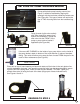
PRESSURE CARTRIDGE FILTER INSTRUCTIONS TOOLS REQUIRED 1. Flat Head Screwdriver 2.
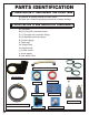
PARTS IDENTIFICATION 1. OPEN CARTON #1 AND UNPACK THE FILTER TANK A. Remove all packing material from filter carton. B. Open tank, remove any packing materials and inspect cartridge. 2. OPEN CARTON #2 AND UNPACK ALL COMPONENTS A. Filter base B. (2) 6’ long filter connection hoses C. (1) Flex pipe with connection fittings D. (4) Stainless steel hose clamps E. Pressure gauge F. Teflon tape G. Straight fitting H. Hardware bag I. (2) Slide valves J. Union adapter K. Side Mount Union C.
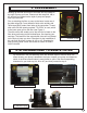
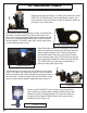
. PRE-ASSEMBLY Hooking up the filter and motor to the base will vary based on the style of pump you have. Please note that steps 4A, 4B, or 4C will help you determine the style of pump and proper hook-up to the base. Prior to attaching the filter or pump to the base, locate one of the slide valves (I). Cover threads of slide valve entirely with Teflon tape (F) to protect from leaks at the connection.
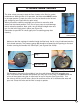
A. CRADLE STYLE MOUNT Pumps with cradles located directly under the motor (see Figure 2) should be aligned with the holes inside the raised area of the base (see Figure 3a). This type of mount will require the use of FOUR mounting bolts from the hardware bag (H). Figure 2 — Cradle style mount pump Cover threads of slide valve entirely with Teflon tape (F) to protect from leaks at the connection. Thread the slide valve into the FRONT of the pump or pump strainer basket if applicable (see Figure 3b).
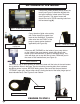
4B. PLASTIC PUMP HOUSING MOUNT Pumps with plastic pump housing mounts (see Figure 7) should be attached by aligning the openings with the two holes outside the raised area (see Figure 8a). This type of mount will require the use of TWO mounting bolts from the hardware bag (H). Figure 7 — Plastic pump housing mount Cover threads of slide valve entirely with Teflon tape (F) to protect from leaks at the connection.
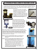
4C. SIDE-MOUNT PUMPS Side-mount pumps (see Figure 12) allow you to attach the pump DIRECTLY to the filter body. Prior to attaching the pump, you must attach the tank to the base in order to determine which set of holes to use for the pump. Figure 12 — Side mount pump Place tank on top of round opening on base and rotate until the holes in the tank bottom line up with the holes in the base. Use remaining mounting bolts from hardware bag (H) to secure in place.
5. ATTACHING FITTINGS & HOSES TO YOUR PUMP & FILTER There are several ways to hook up hoses to your filter and pump and the best way will depend on your set-up. Some pumps have female threads only (inside), some have male threads only (outside) and others may have both or none. There are parts included in CARTON 2 which will allow for set-up with virtually any style of pump. Below are the options available for hook-up based on the threads that your pump has.
If your pump has threads on the outside of the outlet (top of the pump) then you will thread one of the connection fittings directly onto it. Thread opposite side directly onto the “FROM PUMP” port of the filter and hand tighten connection (see Figures 21 & 22). Figure 21 — Attaching flex pipe to filer If your pump ONLY has threads on the inside of the outlet (top of the pump) then you will need to use the union adapter (J).
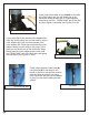
6. USING SLIDE VALVES The slide valves are used to stop the flow of water to the filter for routine maintenance. While the filter is in operation, the slide valves MUST remain in the open position To open the valve, turn the red handle to the left and pull straight up (see Figure 23a for open valve). When you need to clean the cartridge you will have to move the slide valves into the closed position. First, turn off your pump to avoid damage due to excessive pressure.
READ AND FOLLOW SAFETY INSTRUCTIONS! This is the safety alert symbol. When you see this symbol on your system or in this manual, look for one of the following signal words and be alert to the potential for personal injury. ! ! DANGER Warns about hazards that will cause death, serous personal injury, or major property damage if ignored. ! WARNING Warns about hazards that can cause death, serious personal injury, or major property damage if ignored.
GENERAL INFORMATION ! DANGER Hazardous pressure. If filter is improperly disassembled or assembled, it will explode under pressure. To avoid danger of severe injury or major property damage, always follow service instructions in this manual (Pages 11 to 13) when working on filter. ! WARNING Risk of explosion. Never operate this filter system at more than 50 pounds per square inch (50 PSI/345kPa) pressure! • Clean a new pool as well as possible before filling pool and operating filter.
INSTALLATION — GENERAL FILTER LOCATION SHOULD: • Provide space and lighting for easy access for routine maintenance. • Provide adequate ventilation and drainage for pump. • Be reasonably level. • Be as close to pool as possible to reduce line loss from pipe friction. PIPING • Never use pipe joint sealing compound on pipe and fittings that are plastic or may come into contact with plastic. To seal threaded connections on PVC pipe and fittings, use only teflon tape.
ASSEMBLING FILTER Filter Cartridge may shift position during shipping. To make sure cartridge is in place, follow procedure below before using filter. When disassembling filter, place all parts in a clean area. 1. Place filter in a clean area near its permanent location. 2. Remove filter head by turning Locking Ring counter clockwise Figure 1. Remove clamp by lifting straight up over tank. 3. As clamp is turned the Filter Head will rise from the tank body.
START UP ! WARNING HAZARDOUS PRESSURE. Risk of severe injury or major property damage if tank explodes. READ the entire procedure before starting system or disassembling filter. 1. Turn pump OFF before starting procedure. 2. Properly seat filter clamps and securely tighten clamp knobs before proceeding. NOTICE 1. Tightly close plugs on Tank Drain Port (Figure 2). 2. Open air release valve located on top of filter tank head. NOTICE Air trapped inside the filter greatly increases the explosion hazard.
FILTER DISASSEMBLY ! DANGER Hazardous Pressure Releasing either ring with pressure on system will cause tank or tank head to blow off base, causing severe injury or major property damage. NEVER adjust, tighten or loosen ring when tank is under pressure. If filter leaks at the ring, do not adjust the ring. Instead, follow instructions under “Filter Disassembly”, below and “Filter Assembly”, Page 8. ! Regularly inspect clamp assemblies for cracked, corroded or broken welds and worn or stripped threads.
FILTER REASSEMBLY LIFT FILTER ELEMENT STRAIGHT UPWARD TO REMOVE 1. Replace plugs or close valves in Tank Drain and Auxiliary Drain ports. 2. Set filter element on base. 3. Make sure filter element is flush with base of filter to avoid damaging element when you replace the filter head (Figure 3). 4. Inspect and clean the tank flanges and O-Ring seats. If flanges are deformed, cracked or corroded, replace entire filter. 5. Replace Filter Head and Locking Ring assembly on tank. 6.
SPECIAL CLEANING INSTRUCTIONS ! DANGER Risk of fire or explosion. Isolate filter from system before chemical cleaning; rinse filter and elements completely before returning to service. If filter cannot be isolated, remove media and clean at another location. Follow chemical manufacturer’s instructions for use. Do not mix chemicals except as directed by manufacturer. Do not allow cleaning chemicals to mix with or to come in contact with chlorine, bromine, other chemicals, or chemical feed devices.
WINTERIZING ! DANGER Hazardous pressure. To avoid severe injury or major property damage, follow instructions below exactly. Explosion hazard. Purging the system with compressed air can cause components to explode, with risk of severe injury or death to anyone nearby. Use only a low pressure (below 5 PSI), high volume blower when air purging the pump, filter or piping. ! WARNING Filter must be protected from the weather and drained if freezing is anticipated.
LOW FLOW: 1. Element is plugged — see “Special Cleaning Instructions”. 2. Pipe blocked downstream from filter — remove obstruction. 3. Piping too small — replace with larger pipe (consult dealer for recommendation). 4. Pump hair and lint trap is plugged — empty and clean. 5. Pump impeller and diffuser worn — replace with new parts. Consult pump owner’s manual for information. 6. Pump too small for system — replace with larger pump. POOL WATER NOT CLEAR: 1.
FILTER PARTS LIST PART # DESCRIPTION BS BS BS BS BS BS BS BS BS BS BS BS PRC30 PRC60 PRC90 PRC120 PRC150 PRC180 PRC30BD PRC60BD PRC90BD PRC120BD PRC150BD PRC180BD NE635 NE636 BS 40061BLK Hose Adapter 1 1 1 1 1 1 1 1 1 1 1 1 BS PRCBASE Filter Base 1 1 1 1 1 1 1 1 1 1 1 1 AC 26875 Complete LID 1 1 1 1 1 1 1 1 1 1 1 1 AC 26859 Slide Valve 2 2 2 2 2 2 2 2 2 2 2 2 BS 10022 6’ 1/2 Hose 2 2 2 2 2 2 2 2 2 2 2 2 BS 17396GRY Threaded Plug 1 1 1
HYDRO™ ABOVE-GROUND CARTRIDGE FILTER SYSTEM NE635 & NE636 One Year Hydro™ Cartridge Filter System Warranty Registration Card 1745 Wallace Ave, Ste. B St. Charles, IL 60174 1. Hydro™ Cartridge Filter System has a one year warranty against defects in materials and workmanship. To receive the warranty, the card must be filled out completely and returned. 2.