INSTALLATION AND OPERATION MANUAL ELECTRIC GRIDDLE EP514 EP516 EP518 For use in GB & IE 229351-6
MANUFACTURED BY Moffat Limited PO Box 10001 Christchurch New Zealand Ph: (03) 389 1007 Fax: (03) 389 1276 WORLD-WIDE BRANCHES UNITED KINGDOM Blue Seal 67 Gravelly Business Park Gravelly Park Birmingham West Midlands B24 8TQ Ph: (121) 327 5575 Fax: (121) 327 9711 UNITED STATES Moffat Inc 3765 Champion Blvd Winston-Salem North Carolina 27115 Ph: (336) 661 0257 Fax: (336) 661 9546 CANADA Serve Canada 22 Ashwarren Road Downview Ontario M3J1Z5 Toll Free:800 263 1455 Ph: (416) 631 0601 Fax: (416) 631 0315 info@se
Contents Blue Seal Electric Griddle EP514 EP516 EP518 Electric Griddle, Electric Griddle, Electric Griddle, 600mm. 900mm. 1200mm. Introduction ............................................................................................. 2 Specifications ........................................................................................... 3 Model Numbers Covered in this Specification General Electrical Supply Requirements Electrical Connection Dimensions Installation ................................
Introduction We are confident that you will be delighted with your BLUE SEAL ELECTRIC GRIDDLE, and it will become a most valued appliance in your commercial kitchen. To ensure you receive the utmost benefit from your new BLUE SEAL Appliance, there are two important things you can do. Firstly: Please read the instruction book carefully and follow the directions given. The time taken will be well spent.
Specifications Model Numbers Covered in this Specification EP514 - B Electric Griddle 600mm wide Bench Model. EP514 - CB Electric Griddle 600mm wide with Cabinet Base. EP514 - LS Electric Griddle 600mm wide on Leg Stand. EP516 - B Electric Griddle 900mm wide Bench Model. EP516 - CB Electric Griddle 900mm wide with Cabinet Base. EP516 - LS Electric Griddle 900mm wide on Leg Stand. EP516 - RB Electric Griddle 900mm wide with Refrigerated Base. EP518 - B Electric Griddle 1200mm wide Bench Model.
Specifications Electrical Supply Requirements 1-Phase Connection 1P+N+E 230-240V, 50 / 60Hz 7.2 kW MODEL EP514 3-Phase Connection 3P+N+E 400-415V, 50 / 60Hz --------- 30 Amps @ 240 V EP516 --------- 12.0 kW EP518 --------- 18.0 kW L1 L2 L3 L1 L2 L3 - 16.4 16.4 16.4 24.5 24.5 24.5 Amps Amps Amps Amps Amps Amps Electrical Connection WARNING: THIS APPLIANCE MUST BE EARTHED. IF THE SUPPLY CORD IS DAMAGED, IT MUST BE REPLACED BY A SUITABLY QUALIFIED PERSON IN ORDER TO AVOID A HAZARD.
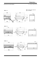
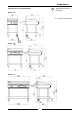
Dimensions Dimensions for Bench Models R EP514 - B R EP516 - B EP518 - B 5 = Rating Plate Location for this option.
Dimensions Dimensions for Cabinet Base Models R EP514 - CB R EP516 - CB EP518 - CB 6 = Rating Plate Location for this option.
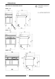
Dimensions Dimensions for Leg Stand Models R EP514 - LS R EP516 - LS EP518 - LS 7 = Rating Plate Location for this option.
Dimensions Dimensions for Refrigeration Base Models R EP516 - RB 130 280 R EP518 - RB 280 8 = Rating Plate Location for this option.
Installation Installation Requirements NOTE: • It is most important that this appliance is installed correctly and that operation is correct before use. Installation shall comply with local electrical and health and safety requirements. • This appliance shall be installed with sufficient ventilation to prevent the occurrence of unacceptable concentrations of health harmful substances in the room, the appliance is installed in.
Installation Assembly C AUTIO N : • This appliance is for professional use and is to be used by suitably qualified / trained persons only. • Only qualified service persons are to carry out installation and servicing of this appliance. All Models All models come pre-assembled. NOTE: This appliance is fitted with adjustable feet (castors) to enable the unit to be positioned securely and level. This should be carried out on completion of the electrical connection.
Installation Commissioning 1. Before leaving the new installation; a. Check the following functions in accordance with the operating instructions specified in the 'Operation' section of this manual. • Check the current draw and loading for the equipment. Refer to the 'Specification' section for the correct electrical requirements. • Check that all the connections are correct and that all cover panels have been re-fitted.
Operation Operation Guide C AUTIO N : • This appliance is for professional use and is only to be used by suitably qualified / trained persons. • Only qualified service persons are allowed to carry out installation and servicing of this appliance. 1. 2. Blue Seal Electrical Griddles have been designed to provide simplicity of operation and 100% safety protection.
Cleaning and Maintenance C AUTIO N : Always turn off the electrical supply at the mains before cleaning. This appliance is not water proof. Do Not use water jet spray to clean interior or exterior of this appliance. General Clean the griddle regularly. A clean appliance looks better, will last longer and will perform better. Carbonised grease on the surface or on the griddle plate will hinder the transfer of heat from the cooking surface to the food. This will result in loss of cooking efficiency.
Cleaning and Maintenance Daily Cleaning 1. 2. 3. 4. 5. The grease drawer should be checked and emptied frequently to prevent overflow and spillage. Remove the grease drawer while still warm so that the grease is in a liquid state. Empty any grease from the drawer and wash thoroughly in the same manner as any cooking utensil. Clean the Control Panel with a damp cloth lightly moistened with a solution of mild detergent and water.
Cleaning and Maintenance a. Remove and clean the grease collection drawer frequently to prevent over spills. b. Clean the griddle surface thoroughly with the supplied scraper tool. c. Allow the plate to cool, then clean the plate with a scrubbing brush, a mild non-abrasive detergent and water. d. Occasionally bleach the plate with vinegar when cold. e. Dry the griddle thoroughly with a dry cloth and polish with a soft dry cloth. f.
Fault Finding This section provides an easy reference guide to the more common problems that may occur during the operation of your equipment. The fault finding guide in this section is intended to help you correct, or at least accurately diagnose problems with your equipment. Although this section covers the most common problems reported, you may encounter a problem not covered in this section.
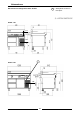
Circuit Schematics EP514 Wiring Schematic REAR SUPPLY ENTRY EARTH STUD M6 8 8 13 15 8 9 9 LABEL 019207 9 13 8 8 8 7 7 6 10 EARTH STUD M6 GRIDDLE PLATE 14 7 7 6 5 3 2 32 22 12 31 21 11 32 1 12 2 THERMOSTAT 229146 4 OVERTEMP THERMOSTAT 229353 1 22 1 NEON AMBER 227963 31 21 11 11 4 P4 3 P3 2 P2 12 NEON GREEN 227962 10 9 9 9 14 EARTH STUD 3/16" SWITCH 1 229145 P1 CONTROL PANEL 17 4
18 16 16 7 1 4 2 8 2 3 7 13 7 P1 P3 P2 3 2 11 12 6 P4 21 22 7 8 4 31 32 SWITCH 1 229145 OVERTEMP THERMOSTAT 229353 EARTH STUD 3/16" 1 11 21 31 1 12 22 32 EARTH STUD M6 15 6 14 10 10 10 NEON GREEN 227962 12 4 1 21 22 7 1 11 12 CONTROL PANEL 1 31 10 32 10 THERMOSTAT 229146 10 NEON AMBER 227963 5 12 7 2 13 7 2 3 4 31 32 SWITCH 1 229145 OVERTEMP THERMOSTAT 229353 4 2 3 GRIDDLE PLATE 8 8 21 22 7 LABEL 229043 P1 P2 P3 P4 11 12
19 18 18 7 1 11 12 4 2 8 2 3 7 15 7 P2 2 P1 P3 3 11 12 6 P4 21 22 7 8 4 31 32 SWITCH 1 229145 OVERTEMP THERMOSTAT 229353 EARTH STUD 3/16" 1 21 31 1 22 32 EARTH STUD M6 17 6 11 11 11 NEON GREEN 227962 14 4 1 31 THERMOSTAT 229146 16 32 NEON AMBER 227963 5 1 21 22 7 1 11 12 2 3 7 15 7 7 8 2 3 4 31 21 32 22 SWITCH 1 229145 OVERTEMP THERMOSTAT 229353 4 2 8 P1 P2 P3 P4 11 12 6 6 10 10 10 NEON GREEN 227962 13 THERMOSTAT 229146
Replacement Parts List Replacement Parts List IMPORTANT: Only genuine authorized replacement parts should be used for the servicing and repair of this appliance. The instructions supplied with the parts should be followed when replacing components. For further information and servicing instructions, contact your nearest authorized service branch (contact details are as shown on the reverse of the front cover of this manual).
Replacement Parts List Griddle Plate Options Griddle Plate Standard Chromed (-C) 600mm 229212 229267 900mm 229248 229270 1200mm 229279 229281 21 Ribbed ON REQUEST, Various options (depending on ribbed section width on LH or RH side).