
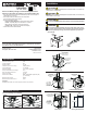
User guide
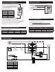

Installation Diagram
COMMON BUSBAR
REMOTE
CONTROL
SWITCH
OPTIONAL
ALARM
STEREO OR OTHER
12V DC DEVICES
BATTERY
LED OUTPUT
OPTIONAL BATTERY SWITCH
Required if
the battery is
over 800 Cold
Cranking Amps (CCA)
ALARM OUTPUT
1
2
3
8 7
4
5
6
10A FUSE
FUSE*
See Wire Size
and Fuse
Rating Chart
above
FUSE
Connection Legend
DC Positive
DC Negative (Ground)
Optional
Control
+
-
NEG
POS
FUSE
m-LVD Connections
Function
A Battery
B Load
1 Ground
2 Remote Switch
3 Alarm Output
4 LED Output
• The Installation Diagram illustrated below represents a common installation and is
not meant to be a guide for wiring a specic vessel.
Caution: Disconnect battery connections before beginning the installation.
Reconnect after the installation is complete.
Use the wire sizing chart below to select the appropriate wire sizes. Consult an
ABYC certied electrician for proper fuse placement and sizing.
* Larger wire sizes may be required to minimize voltage drop in long wire runs.
For more information please use the Circuit Wizard at www.circuitwizard.bluesea.com.
Wire Size and Fuse Rating Chart*
Amps Min. Wire Size* (AWG) Fuse Rating Min. Wire Size* (Metric)
≤30 #10 40A-50A 6 mm²
≤50 #8 60A-65A 10 mm²
≤65 #6 90A-100A 16 mm²
Electrical Connections
m-LVD Connection Table
Disconnect Voltage Adjustment
Disconnect Voltage LED Flash Count
Factory Default:
12.1V
5
11.9V 4
11.7V 3
11.5V 2
11.3V 1
• Press and hold the OVERRIDE position of the remote control
switch for 10 seconds to enter adjustment mode. Adjustment
mode can only be entered in the Connected or Disconnected
states, not in the Low Voltage Warning state. LED will
beginaashpatterntoindicatethecurrentDisconnect
voltage setting (see table below).
Disconnect Voltage Adjustment Table
• Press and release OFF to decrease the Disconnect
voltagesettingin0.2Vincrementsdowntoaminimumof11.3V(1ash).
• Press and release OVERRIDE to increase the Disconnect
voltagein0.2Vincrementsuptoamaximumof12.1V(5ashes).
• Whenyouaresatisedwithyourselection,releasethe switch, and wait
approximately 20 seconds, the m-LVD will save the new Disconnect
Voltage Setting, and automatically return to normal operation.
m-LVD Normal Operation Status Chart
LED Alarm Relay Status
OFF Solid OFF Closed Connected
ON Solid ON Closed Low Voltage Warning
Double Flash OFF Open Disconnected
m-LVD Normal Operation Status Chart
Operation during Low Voltage Warning or when Disconnected
• Press OVERRIDE
to temporarily delay circuit disconnect for 10 minutes.
• Press OVERRIDE or OFF
to silence alarm (optional alarm required).
• Press OFF
to temporarily disconnect circuits until voltage rises.
Remote Control Switch