
Installation & Operation Instructions

CONFIGURATION SETTINGS
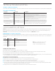
FUNCTION #2 OCCUPANCY TIME DELAY
Unlike wired occupancy sensor systems, the time frame between when occupancy was detected last and connected lights turning off is a setting that is maintained in the power pack load
controller and not the sensor itself. This arrangement enables the sensors to conserve battery life. See additional notes below for more information on wireless sensor communications to
a power pack.
SETTING # DESCRIPTION FUNCTION #
2 1 Min
3 5 Min
4 10 Min Default for all models
5 15 Min
6 20 Min
7 30 Min
CHANGING THE OCCUPANCY TIME DELAY
1Read through the above list and note the number of the desired setting (e.g. 4 = 10 minutes).
2 Press and release the unit’s pushbutton 2 times, then wait 2 seconds.The White LED will blink back the number of the current setting (repeats 3x before exiting).
3 Interrupt blink back by pressing the button the number times equal to the new desired setting (e.g. 5 = 15 minutes).
4 The LED will blink back the new setting number as conrmation and will be saved after three conrmations. After the third conrmation sequence, a successful save will be indicated by
two sets of rapid White ashes. If the Blue LED rapid ashes twice, save was unsuccessful and process should be started over.
ADDITIONAL NOTES ON OCCUPANCY TIME DELAY
à By default, every ~60 seconds a sensor transmits whether or not occupancy was detected during the previous period.
à Referred to as the sensor’s “heartbeat”, this period can be reduced to ~30 seconds although this will decrease expected battery life.
à If a sensor transmitted “unoccupied” at its last heartbeat, any new occupancy detection event will be transmitted immediately.
à If a sensor transmitted “occupied” at its last heartbeat, new occupancy events will only be transmitted at the heartbeat interval, thus conserving battery life.
à The wirelessly linked wall switch load controller and/or power pack maintains a master time delay that is reset every time a linked sensor reports occupancy. Lights will be switched
off once all linked sensors have continously reported unoccupied for the duration of the time delay.
à If a power pack does not receive a heartbeat transmission from a linked sensor for 2 minutes it will consider itself occupied.
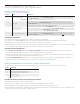
SWX-950 series power packs have many congurable functions depending on the specic model. All functions setting values can be accessed and changed by pressing the unit’s push-
button and observing the LEDs feedback. The functions common to all SWX-950 series power packs are listed rst below. Functions present in models with the dimming option (e.g.
SWX-950-D2) are listed next and the function(s) that are present with the hybrid wireless/wired option (e.g. SWX-950-AX) are listed last.
TESTING & TROUBLESHOOTING
TESTING CONNECTED LIGHTING
To test the unit’s control of connected lighting, press and release the push button (located next to LED) one time. Lights should toggle if the unit is operating and wired to lighting properly.
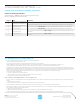
LED BLINKOUT BEHAVIOURS
LED BEHAVIOR DESCRIPTION NOTES/REMEDY
Continuous WHITE blinking “heartbeat” Normal operation
Repeating double BLUE ashing Power supply is overloaded.
1. Check for miswiring causing a short on the red low voltage wire.
2. Remove low voltage load from the red wire (i.e. connected sensors, secondary relay packs, or
switches) until the BLUE double ash stops.
Continuous BLUE ahsing Power present on both relay wires
Check wiring going to the blue relay wires on the power pack. Specically, ensure there is not line
power present on both wires when power pack is disconnected.
Continuous WHITE, BLUE ashing Wireless Pairing Mode
To exit pairing mode, press the button one time and release. The LED should return to continous
WHITE “heartbeat”
Continuous WHITE, BLUE ashing with
periodic WHITE blinking
Wireless Pairing Mode w’ Linked Device
Count
The number of periodic WHITE blinks reects the number of linked devices. To exit pairing mode,
press the button one time and release. The LED should return to continous WHITE “heartbeat”
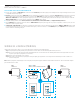
NOTE: A 5-10 second time delay sensor test mode
can be initiated from a sensor in order to test
coverage. Test mode will expire after 10 minutes.