
Installation & Operation Instructions

INSTALLATION INSTRUCTIONS
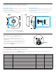
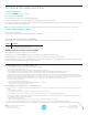
MOUNTING OPTIONS
A. Chase nipple & lock nut (included) for mounting unit to ceiling tile or 1/2” knockout in
junction box. See Side Diagram below.
B. Screw holes for directly mounting to ceiling surface, 3-1/2” (trade size) octagon box, or
mud ring with 2-3/4” spaced ears. See Front Diagram below.
INSTALLATION NOTES
• If mounting to ceiling tile, use the serrated end of the chase nipple to cut a 7/8” hole.
Then thread the wires through nipple prior to screwing into rear of sensor. Install and
tighten lock nut as needed.
• To install cover, line up dimples with indents on sensor and turn clockwise.
CHASE NIPPLE
PROGRAMMING BUTTON
LOCK NUT
COVER
FRONT SIDE
SENSORSENSOR
SERRATED END FOR
CUTTING THROUGH
CEILING TILE
CHASE NIPPLE & LOCK NUT INCLUDED FOR MOUNTING
TO CEILING TILE OR 1/2” KNOCKOUT IN JUNCTION BOX
4”
1.25”
SCREW HOLES FOR DIRECTLY MOUNTING TO:
• CEILING SURFACE
• 3-1/2” (TRADE SIZE) OCTAGON BOX
• MUD RING WITH 2-3/4" SPACED EARS
2.75”
Note: If mounting to a Single Gang Mudring, Handy Box, or 4”
Octagon Box, a trim ring is required. Part Number: SWX-299-JP.
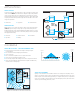
à The sensor runs on one CR123(A) Lithium Battery (included).
à Install battery prior to mounting sensor. Polarity is indicated on the battery
compartment door.
à If the sensor’s battery life reaches 10%, all wirelessly linked load controllers will
blink lights on/off/on upon initial occupancy as a replacement warning.
à Replacement batteries are available at most retailers or home centers where
batteries are sold or from SENSORWORX.
MOUNTING
BRACKET
CHASE NIPPLE
BATTERY
COMPARTMENT
BATTERY
COMPARTMENT
BATTERY
COMPARTMENT
LOCK NUT
CHASE NIPPLE
LOCK NUT
LOCKING 3-POSITION
TILT ADJUSTMENT
MOUNTING
BRACKET
LOCKING 3-POSITION
TILT ADJUSTMENT
SERRATED END
FOR CUTTING
THROUGH
CEILING TILE
SERRATED END FOR CUTTING
THROUGH CEILING TILE
BATTERY INFORMATION
COMPATIBLE WIRELESS DEVICES
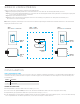
The below chart lists the devices that can be used in a SENSORWORX wireless application. Note that sensors and remote switch & dimmer devices are transmit only devices and
therefore must be linked to a load controller for switching or dimming of lighting.
MODEL # DESCRIPTION WIRELESS TYPE POWER TYPE
SWX-201-B Small Motion 360° Sensor, PIR Transmit Battery
SWX-401-B Wide View Sensor, PIR Transmit Battery
SWX-402-B Long Range Hallway Sensor, PIR Transmit Battery
SWX-851-xx Wall Switch Load Controller, No Neutral Required, <xx = color> Transmit & Receive 120-277 VAC
SWX-852-B-xx Remote Switch (On/Off), <xx = color> Transmit Battery
SWX-854-B-xx Remote Dimming Switch (On/Off, Raise/Lower), <xx = color> Transmit Battery
SWX-950 Power Pack Load Controller, 20A Receive 120/277 VAC
SWX-950-D2 Power Pack Load Controller, 20A, 0-10V Dimming Receive 120/277 VAC
SWX-950-AX Hybrid Wireless/Wired Power Pack Load Controller, 20A Transmit & Receive 120/277 VAC
SWX-950-AX-D2 Hybrid Wireless/Wired Power Pack Load Controller, 20A, 0-10V Dimming Transmit & Receive 120/277 VAC