
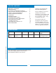
Specifications


INSTALLATION (continued)
5
NOTE: This equipment must
be installed to comply with
applicable federal, state and lo-
cal plumbing codes and or-
dinances.
WARNING:
SHOCK HAZARD
Brewer must be properly
grounded to prevent possible
shock hazard. DO NOT as-
sume a plumbing line will pro-
vide such a ground. Electri-
cal shock will cause death or
serious injury.
IMPORTANT:
Supply power must match
nameplate for voltage and
phase. Connecting to the wrong
voltage will damage the brewer
or result in decreased perfor-
mance. Such damage is not
covered by warranty.
IMPORTANT:
Do not connect brewer to
electrical power until you are
ready to ll the tank. See in-
structions on page 6.
A water shut-off valve should be installed on the incoming water
line in a convenient location (Use a low restriction type valve,
such as a 1/4-turn ball valve, to avoid loss of water ow thru the
valve.
NSF requires that the brewer be able to be moved for cleaning
underneath. A ex line or loops of copper tubing will satisfy this
requirement. See Figure 2 below.
In some areas, local codes require a backow preventer (check
valve) to be installed on the inlet water line. If a backow
preventer is used, you must install a water hammer arrester
in the incoming line, between the backow preventer and
the brewer inlet, as far away from the brewer as space will allow.
This will relieve the excessive back pressures that can cause
faucet leaks and solenoid malfunctions.
ELECTRICIAN’S INSTALLATION INSTRUCTIONS
REFER TO ELECTRICAL SPECIFICATIONS - Page 1
Check the nameplate to determine correct electrical service
required for this installation.
IMPORTANT: Before connecting to electricity, make sure the
brewer is connected to the water supply.
IMPORTANT:
For power supply connections use COPPER WIRE only. Wir-
ing must be suitable for at least 75ºC. This brewer requires a
dedicated electric circuit.
Models 8752 must be wired by an electrician, and require a
115/230V 20A circuit (50/60 Hz, 2 hot legs / 1 neutral leg, plus
ground). Remove rear panel to gain access to terminal block.
Green terminal must be connected to a suitable building ground.
Circuit must be capable of 4000 Watts. See gure 3 at right.
IMPORTANT: Wiring must be installed in approved solid or
exible conduit, and must be secured to the brewer with a strain
relief (to be provided by the installer).
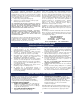
Fig. 2 Water Supply Installation
Fig. 3 Electrical Installation
IL1651
IL1652
COPPER LOOPS OR
FLEX LINES
(PROVIDED BY
PLUMBER)
SOLENOID
WATER INLET
FITTING
WATER
SUPPLY
SHUT-OFF VALVE
(PROVIDED BY
PLUMBER)
FLOW
STRAINER
WASHER
605 p/n 2M-70988 8752 Owmers Manual
605 p/n 2M-70988 8752 Owmers Manual