
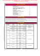
Specifications
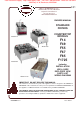

301 p/n 2M-307588 Owners Manual Counter Top Standard Electric Fryers
5
INSTALLATION (continued)
WARNING:
ELECTRIC SHOCk HAZARD
All servicing requiring access to non-insulated electrical components must be performed by a
factory authorized technician.
DO NOT open any access panel which requires the use of tools. Failure to follow this warning
can result in severe electrical shock.
CAUTION:
RISk OF
DAMAGE
DO NOT connect or energize
this appliance until all
installation instructions are
read and followed. Damage
to the appliance will result
if these instructions are not
followed.
CAUTION:
ELECTRIC
SHOCk HAZARD
The ground pin of the power
cord plug is part of a system
designed to protect you from
electric shock in the event of
equipment damage.
DO NOT cut the ground pin
from the power cord plug
in order to t an existing
receptacle;
DO NOT twist a blade of the
power cord plug in order to t
an existing receptacle.
Contact a licensed electrician
to install an appropriate
electrical circuit and
receptacle.
CAUTION:
ELECTRIC
SHOCk HAZARD
The ground lug of F55,
F67 and F85 fryers must
be connected to a suitable
building electric ground.
IMPORTANT:
Damage due to being
connected to the wrong
voltage or phase is NOT
covered by warranty.
F14 and F49 FRYER ELECTRICAL INSTALLATION
This fryer is equipped with a cord and plug, and requires a properly
installed matching receptacle. Contact a licensed electrician to install
an appropriate electric circuit and grounded receptacle.
Be sure the TEMPERATURE
CONTROL KNOB is turned to the
OFF position, then plug the POWER
CORD into the proper receptacle.
F55, F67 and F85 FRYER
ELECTRICAL INSTALLATION
These fryers must be connected directly to the electric circuit. Conduit
and strain relief must be provided by the electrician. Refer to fryer
nameplate for circuit voltage and amperage requirements.
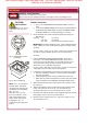
Raise the element head, remove the frypot and the cover at the rear
of the fryer to gain access to the terminal block. The electrical inlet is
provided by a knock-out in the rear panel.
If an equipment shutdown interface is required by local re code,
the ame sensor terminal block may be accessed by removing the
back panel. Replace the jumper of the terminal block with wiring to a
normally closed contact of the building re management system.
DO NOT connect power to the ame sensor terminal block. Wiring and
contacts must be capable of handling 20 amps.
F67 and F85 fryers are shipped from the factory wired for three phase.
Refer to included wiring diagram for conversion to single phase
operation.
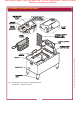
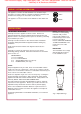
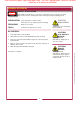
Fig. 3 Fryer Power Plug and
Receptacle Conguration
Total Restaurant Supply - https://totalsupply1.com - Toll Free 1-800-944-9304 - Local 507-288-9454
2940 Hwy 14 W, Rochester, MN 55901