
Specifications

TOS9220/9221 Connections 3-13
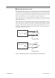
high-voltage digital voltmeter or the TOS1200 current calibrator, to the
scanner. Otherwise, the ammeter will be short-circuited.
For more information, see “Setting LOW/GUARD for the GND” in Chapter
3 “Basic Operations” of the Operation Manual for the TOS9200/9201
Testers.
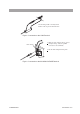
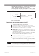
Fig.3-8 Connection Failure
Procedure for connecting the scanner to the DUT
1. Turn OFF the POWER switch of the tester proper.
2. Confirm that the analog voltmeter on the tester proper reads “0.”
3. Before making connections, check that the test leadwires in use do not
contain broken wires and that the coating is not damaged.
4. Connect the test leadwires to the output terminals of channels to be
used for a test.
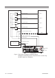
The connection to the output terminals is the same as that to the IN HIGH
VOLTAGE terminal. See Fig. 3-3.
If the contact check function is not used, it is not necessary to connect the test
leadwires to both the A and B output terminals as shown in Fig. 3-7.
5. Connect the test leadwires to the DUT.
6. Confirm that the test leadwires are connected properly and securely.
Confirm that the cable clamper has been securely fastened.
When two or more scanners have been connected in parallel, note the relation-
ship between the channels viewed from the tester proper and those of each
scanner. Confirm that the channels set on the tester proper agree with those of
the test points to which the test leadwires have been connected.
• To ensure safety, do not connect test leadwires to the output terminals of a
channel not being used for a test. If test leadwires are connected to such
a channel, set that channel to LOW. For more information, see the follow-
ing notes:
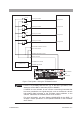
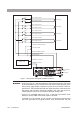
Relay on
Test point A
CH1 A output terminal
CH1 B output terminal
RL 1a
RL 1b
DUT
TOS9221
WARNING