
Specifications

3-12
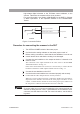
Connections
TOS9220/9221
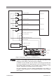
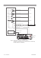
Fig.3-7
T
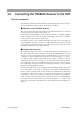
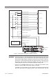
est System Using the
T
OS9221 Scanner
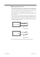
•
As sho
wn in
Fig.
3-7
, the test leadwire of a B-output ter
minal is connected
to the test leadwire of an A-output ter
minal at the corresponding test point.
Dur
ing a test, high v
oltage is applied to a point pr
ior to the rela
y of a B-out
-
put ter
minal.
The B-output ter
minals are output ter
minals connected to the
low-voltage side, but they should be handled in the same way as the A-
output terminals, which are connected to the high-voltage side.
• If there is a possibility that the DUT, jig, or the like is grounded, never
attempt to set the GND of the tester proper to GUARD.
If GUARD is to be selected, do not connect a measuring instrument that
has been grounded at one signal terminal, such as the Kikusui 149-10A
Test point A
Test point B
Test point C
Test point D
CH1 A output terminal
OUT HIGH VOLTAGE terminal
SCANNER IN terminal
SCANNER OUT terminal
OUT LOW terminal
IN HIGH VOLTAGE terminal
HIGH VOLTAGE
terminal
IN LOW terminal
CH1 B output terminal
RL 1a
RL 1b
CH2 A output terminal
CH2 B output terminal
RL 2a
RL 2b
CH3 A output terminal
CH3 B output terminal
RL 3a
RL 3b
CH4 A output terminal
CH4 B output terminal
RL 4a
RL 4b
Control circuit
DUT
TOS9221
TOS9200/9201
LOW terminal
SCAN terminal
WARNING