
Specifications

TOS9220/9221 Connections 3-11
3.3 Connecting the TOS9221 Scanner to the DUT
The following describes important points that must be understood, such as the oper-
ation of the TOS9221 scanner, before connecting it to the DUT.
■
Operation of the
T
OS9221 Scanner
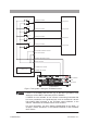
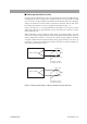
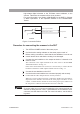
The state of the connections of all four channel outputs of the
T
OS9221 scanner to
the test points of the DUT is sho
wn in
Fig. 3-7
.
As can be seen from the fi
gure, the
A-terminal side of each channel output is con
-
nected to the HIHG
V
OL
T
A
GE terminals of the scanner
, while the B-terminal side
is connected to the LO
W terminals.
In
Fig. 3-7
, the
T
OS9200/9201 tester can set each channel to a potential of HIGH,
LO
W
, or OPEN, and can conduct an
A
C/DC withstanding v
oltage test or insulation
resistance test on an
y of four test points
A to D.
F
or e
xample, when a test is conducted with CH1 (test point
A) set to the high-v
olt
-
age side (HIGH), CH2 (test point B) set to OPEN, and CH3 (test point C) and CH4
(test point D) set to the lo
w-v
oltage side (LO
W), the relays RL 1a, RL 3b, and RL
4b within the
T
OS9221 scanner will be turned on.
■
Contact c
hec
k function
The contact check function checks whether test leadwires properly contact the out
-
put terminals of each channel to the corresponding test point of the DUT
. It is also
capable of detecting a brok
en wire in a test leadwire, contact f
ailure, or a f
aulty
relay within the scanner
.
Pressing the ST
AR
T switch of the
T
OS9200/9201 tester with the contact check
function set to ON enables the contact check to be conducted before a test is started.
The tester proper turns on both output relays “a” and “b” of the scanner for e
v
ery set
channel, applies a v
oltage of approx. 2
V DC, and measures the current to check
continuity between the test leadwires and the DUT
. See
Fig. 3-7
.
As an e
xample, assume that test point
A is set to the high-v
oltage side (CH1:HIGH)
and test point C is set to the lo
w-v
oltage side (CH3:LO
W). F
or information on the
procedure for confi
guring the channels, see the Operation Manual for the
T
OS9200/
9201
T
esters.
Pressing the ST
AR
T switch in this condition causes the “READ
Y” display on the
LCD to go of
f and turns on relays RL 1a and RL 1b
.
This enables the
T
OS9200/
9201 tester to check the continuity between the CH1 output terminals and test point
A. Relays RL 3a and RL 3b are then turned on, enabling the tester proper to check
the continuity between the CH3 output terminals and test point C. Before starting a
test, the tester proper performs the contact check in channel order in this w
ay to
check the continuity of all the channels set to HIGH or LO
W
. F
or the channel under
contact check, the LED lights up in orange. F
or a channel set to OPEN, no contact
check will be conducted.
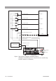
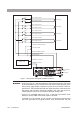
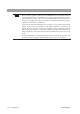
If a connection f
ailure occurs in the wiring between the scanner and DUT
, as sho
wn
in
Fig. 3-8
, or a test leadwire contains a brok
en wire, no current fl
o
ws between the
CHxA and CHxB output terminals.
Thus, the
T
OS9200/9201 tester determines that
contact f
ailure has occurred and displays “
→←
F
AIL” at the upper right of the
LCD.
The tester stops the contact check at the f
ailed channel, and the LED for that
channel lights up in orange.