
Specifications

3-10
Connections
TOS9220/9221
Pr
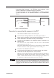
ocedure f
or connecting the scanner to the DUT
1.
T
ur
n OFF the PO
WER s
witch of the tester proper
.
2.
Confi
r
m that the analog v
oltmeter on the tester proper reads
“0.
”
3.
Bef
ore making connections
, chec
k that the test leadwires in use do not
contain brok
en wires and that the coating is not damaged.
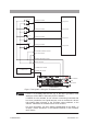
4.
Connect the test leadwires to the output ter
minals of the channels to be
used f
or a test.
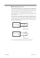
The connection to the output terminals is the same as that to the IN HIGH
V
OL
T
A
GE terminal. See
Fig. 3-3
.
5.
Connect the test leadwires to the DUT
.
6.
Confi
r
m that the test leadwires are connected proper
ly and securely
.
Confi
rm that the cable clamper is securely f
astened.
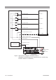
When tw
o or more scanners ha
v
e been connected in parallel, pay attention to
the relationship between the channels vie
wed from the tester proper and those
of each scanner
. Confi
rm that the channels set on the tester proper agree with
those of the test points to which the test leadwires ha
v
e been connected.
• To ensure safety, do not connect the test leadwires to the output terminals
of a channel not used for a test. If test leadwires are connected to such a
channel, set that channel to LOW. For more information, see the following
notes.
• The test voltage applied to the channels set to HIGH leaks into the output termi-
nals of a channel that has been set to OPEN on the tester proper, through stray
capacitances within the scanner. Moreover, if test leadwires have been connected
to a channel set to OPEN, the voltage also leaks to its output terminals through
stray capacitance between the test leadwires.
To prevent the unintentional application of voltage to a test point by this leakage
voltage, do not connect test leadwires to the output terminals of a channel set to
OPEN. However, for tests that are conducted by switching voltage application
points in turn with test leadwires connected to multiple test points, such uninten-
tional application of voltage can be prevented by setting channels irrelevant to the
test to LOW.
• To clearly indicate the correspondence between the connected test leadwires and
channels, attach the supplied channel-indication seals to the test leadwires.
WARNING
NOTE