
Specifications

TOS9220/9221
Connections
3-7
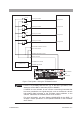
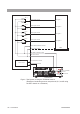
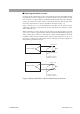
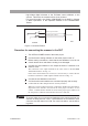
Fig.3-4
T
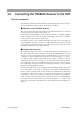
est System 1 Using the
T
OS9220 Scanner
•
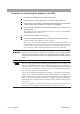
If there is a possibility that the DUT
, jig, or the lik
e is g
rounded, ne
v
er
attempt to set the GND of the tester proper to GU
ARD
.
If GU
ARD is to be selected, do not connect a measur
ing instr
ument that
has been g
rounded at one signal ter
minal, such as the Kikusui 149-10A
high-v
oltage digital v
oltmeter or the
T
OS1200 current calibr
ator
, to the
scanner
.
Otherwise
, the ammeter will be shor
t-circuited.
F
or more inf
or
mation, see item
“Setting LO
W/GU
ARD f
or the GND ”
in
Chapter 3 “Basic Operations” of the Operation Manual for the TOS9200/
9201 Testers.
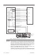
Test point A
Test point B
Test point C
Test point D
CH1 output terminal
OUT HIGH VOLTAGE terminal
SCANNER IN terminal
SCANNER OUT terminal
OUT LOW terminal
IN HIGH VOLTAGE terminal
HIGH VOLTAGE
terminal
IN LOW terminal
RL 1a
RL 1b
CH2 output terminal
RL 2a
RL 2b
CH3 output terminal
RL 3a
RL 3b
CH4 output terminal
RL 4a
RL 4b
Control circuit
DUT
TOS9220
TOS9200/9201
LOW terminal
SCAN terminal
WARNING