
Specifications

3-6 Connections TOS9220/9221
3.2 Connecting the TOS9220 Scanner to the DUT
Prior to connection
The following describes important points that must be understood, such as the oper-
ation of the TOS9220 scanner, before connecting it to the DUT.
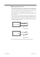
■
Operation of the
T
OS9220 Scanner
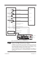
The state in which all four
-channel outputs of the
T
OS9220 scanner are connected
to the test points of the DUT is sho
wn in
Fig. 3-4
.
In this fi
gure, the
T
OS9200/9201 tester can set each channel to a potential of HIGH,
LO
W
, or OPEN, and conduct an
A
C/DC withstanding v
oltage test or insulation
resistance test on an
y of four test points
A to D.
F
or e
xample, when a test is conducted with CH1 (test point
A) set to the high-v
olt
-
age side (HIGH), CH2 (test point B) set to OPEN, and CH3 (test point C) and CH4
(test point D) set to the lo
w-v
oltage side (LO
W), the relays RL 1a, RL 3b, and RL
4b inside the
T
OS9220 scanner will be turned on.
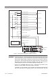
■
Contact c
hec
k function
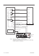
The
T
OS9220 scanner does not ha
v
e a contact check function for checking the con
-
tacts between the DUT and test leadwires. Ho
we
v
er
, the
T
OS9200/9201 tester can
acti
v
ate the contact check function for the
T
OS9220 scanner
. In this case, before
conducting a test the
T
OS9200/9201 tester turns on both output relays “a” and “b”
of a channel of the scanner through which the test v
oltage is output, to check the
continuity up to those relays. See
Fig. 3-4
.
As an e
xample, assume that test point
A
is set to the high-v
oltage side (CH1:HIGH) and test point C is set to the lo
w-v
oltage
side (CH3:LO
W). F
or the procedure for confi
guring channels, see the Operation
Manual for the
T
OS9200/9201
T
esters.
Pressing the ST
AR
T switch in this condition causes the READ
Y display on the LCD
to go of
f and turns on relays RL 1a and RL 1b
.
This enables the
T
OS9200/9201
tester to conduct a contact check on CH1. Relays RL 3a and RL 3b are then turned
on, enabling a contact check on CH3.
The tester proper performs contact checks in
channel order in this w
ay
, to check the continuity of all channels set to HIGH or
LO
W
. If a relay within the scanner f
ails or a brok
en wire e
xists, the
T
OS9200/9201
tester determines that contact f
ailure has occurred and displays “
→←
F
AIL” at the
upper right of the LCD.
The LED of the channel that has f
ailed will light up in
orange.