
Specifications


TOS9220/9221
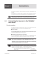
Connections
3-3
Pr
ocedure f
or connecting the scanner
s to the
T
OS9200/9201 tester
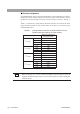
The follo
wing pro
vides an e
xample in
v
olving the connection of three
T
OS9220/
9221 scanners to the
T
OS9200/9201 tester
. See
Fig. 3-1
and
T
able 3-2
.
•
When connecting four
T
OS9220/9221 scanners, connect the 4
th
scanner to the 3
rd
scanner in the same w
ay as the 1
st
and 2
nd
scanners and the 2
nd
and 3
rd
scanners in
Fig. 3-1.
1.
T
ur
n OFF the PO
WER s
witch of the tester proper
.
2. Confirm that the analog voltmeter on the tester proper reads “0.”
3. Before making connections, check that the cables in use do not contain
a broken wire and that the coating is not damaged.
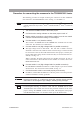
4. Connect cables 1 to 3 (interface cables).
The scanner’s SCANNER IN and SCANNER OUT terminals use the same
connectors. Be careful not to confuse them.
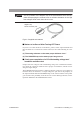
5. Connect cables 4 to 6 (high-voltage leads for parallel connection).
The high-voltage leads are directional. The end with a smaller connector
should be connected to IN, while the other end with a larger connector should
be connected to OUT (or the LOW terminal of the tester proper). Securely fas-
ten the cables using fixing metals to ensure that they are not disconnected acci-
dentally. See Fig. 3-2.
When connecting the high-voltage leads for parallel connection, be sure to
connect them first to the LOW side for the number of scanners, then to the
HIGH VOLTAGE side.
6. Connect cables 7 to 9 (high-voltage leads for parallel connection).
Each IN HIGH VOLTAGE terminal has a cable clamper to prevent accidental
disconnection. For connection to this terminal, see Fig. 3-3.
7. Confirm that each cable is connected properly and securely.
In addition, confirm that the GND wire of the AC power cord or the protective
conductor terminal is securely grounded.
• Improper connection of a cable may cause the scanner chassis and the
entire DUT to be charged to high voltages, thereby posing a danger.
• Connecting/disconnecting an interface cable with the POWER switch of the
TOS9200/9201 tester turned ON activates the protection function of the tester
proper, causing “SCANNER” to flash on the LCD. This brings the tester proper
into PROTECTION status. To cancel this status, press the STOP switch.
NOTE
WARNING
NOTE