
Specifications


TOS9220/9221 Connections 3-1
Chapter 3
Connections
This chapter describes the connections between the scanner, TOS9200/9201 tester,
and DUT.
For information on operations such as setting the scanner output after all connec-
tions have been made, see the Operation Manual for the TOS9200/9201 Testers.
• This scanner is a dedicated option for the TOS9200 and TOS9201 withstanding
voltage/insulation resistance testers. It cannot be connected to other testers.
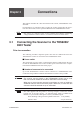
3.1 Connecting the Scanner to the TOS9200/
9201 Tester
Prior to connection
The following describes important points that must be understood before the
TOS9220/9221 scanner is connected to the TOS9200/9201 tester.
■
P
o
wer s
witc
h
The scanner has no po
wer switch. Connecting the interf
ace cable between the scan
-
ner and the
T
OS9200/9201 tester causes scanner po
wer to be turned on in conjunc
-
tion with the PO
WER switch of the tester proper
.
■
Number of scanner
s to be connected
Up to four
T
OS9220/9221 scanners can be connected to a
T
OS9200/9201 tester
.
Connection using both the
T
OS9220 and
T
OS9221 scanners is also possible.
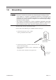
•
The scanner ma
y be placed on the
T
OS9200/9201 tester
, b
ut no more
than one scanner should be stac
k
ed on the tester to ensure saf
ety
.
When tw
o or more scanners are used, mount them on a r
ac
k or install an
y
additional scanners ne
xt to the tester proper
.
Moreo
v
er
, no more than tw
o
scanners should be stac
k
ed on top of each other
.
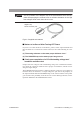
•
The cable supplied with the product is not long enough to connect the scanner
located ne
xt to the tester proper
.
An optional longer cable is a
v
ailable from
Kikusui. If you need this cable, please contact your Kikusui agent.
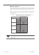
TL04-T
OS high-v
oltage leads for parallel connection
1.5 m [83000]
Interf
ace cable
2 m [85-50-0140]
NOTE
WARNING
NOTE