
Specifications


2-4
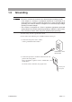
Precautions on Handling
TOS9220/9221
2.4
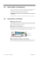
Daily Checking
T
o a
v
oid accidents, confi
rm at least the follo
wing before starting operation.
Common items f
or both the
T
OS9220 and
T
OS9221 scanners
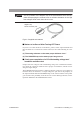
•
The scanner and tester is connected to an ear
th g
round.
•
The coating of the high-v
oltage test leadwire is free from cr
ac
ks
, fi
s
-
sures
, and breakage
.
•
The high-v
oltage test leadwire is not brok
en.
F
or the
T
OS9220 scanner
•
When a test is star
ted at a test v
oltage of 0
V with the contact chec
k
function set to ON in the tester proper
, a CONT
A
CT F
AIL judgment m
ust
not be made
.
(This inspection chec
ks contin
uity up to the output rela
ys within the scan
-
ner
.
F
or more inf
or
mation, see
"
Contact chec
k function
"
in
"3.2 Connect
-
ing the
T
OS9220 Scanner to the DUT"
.)
•
When the output v
oltage is increased g
r
adually with the ends of the test
leadwires across the channel used f
or a test short-circuited, an UPPER
FAIL judgment must be made.
For the TOS9221 scanner
• Short-circuit the ends of the low-voltage test leadwire (output terminal B)
and high-voltage test leadwire (output terminal A) at each channel.
Then, when a test is started at a test voltage of 0 V with the contact
check function of the tester proper set to ON, a CONTACT FAIL judg-
ment must not be made.
• Open the ends of the low-voltage test leadwire (output terminal B) and
high-voltage test leadwire (output terminal A) at each channel. Then,
when a test is started at a test voltage of 0 V with the contact check func-
tion of the tester proper set to ON, a CONTACT FAIL judgment must be
made.
• When the output voltage is increased gradually with the ends of the test
leadwires across the channel used for a test short-circuited, an UPPER
FAIL judgment must be made.