
Specifications


1-6
Setup
TOS9220/9221
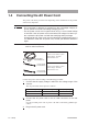
1.4
Connecting the AC Power Cord
The po
wer cord that is pro
vided v
aries depending on the destination for the product
at the f
actory-shipment.
•
This instr
ument is designed to oper
ate from the o
v
er
v
oltage categor
y II.
Do not oper
ate it from the o
v
er
v
oltage categor
y
III
or
IV
.
•
The A
C po
w
er cord f
or 100
V system sho
wn in
Fig.
1-4
has a r
ated v
oltage
of 125
V
A
C
.
If this A
C po
w
er cord is used at the line v
oltage of a 200
V sys
-
tem, replace the A
C po
w
er cord with that satisfying that line v
oltage
.
An appropr
iate A
C po
w
er cord m
ust be selected b
y qualifi
ed personnel.
If
it is diffi
cult to obtain the A
C po
w
er cord, consult y
our Kikusui distr
ib
utor/
agent
•
Do not use the A
C po
w
er cord pro
vided with the product as a A
C po
w
er
cord f
or other instr
uments
.
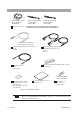
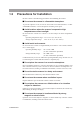
Fig.1-4
A
C po
w
er cord
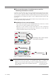
Connect the po
wer cord according to the follo
wing procedure:
1.
Confi
r
m that the supply v
oltage is within the line v
oltage r
ange of the
scanner.
The AC power that can be input is as follows:
2. Connect the AC power cord to the AC LINE connector on the rear
panel.
Use the provided power code or power code that is selected by qualified per-
sonnel.
3. Plug in the AC power cord.
Power cord for 100 V system
Rated voltage: 125 VAC
Rated current: 10 A
Power cord for 200 V system
Rated voltage: 250 VAC
Rated current: 10 A
Nominal voltage range Allowable voltage range Frequency range
100 V to 120 V AC 85 V to 132 V AC 47 Hz to 63 Hz
200 V to 240 V AC 170 V to 250 V AC 47 Hz to 63 Hz
WARNING
[85-AA-0003]
PLUG:NEMA5-15
[85-AA-0005]
PLUG:CEE7/7
[85-10-0790]
PLUG:GB1002