
Specifications


1-4
Setup
TOS9220/9221
■
Do not use the scanner in locations near a sensitive
measuring instrument or receiver
.
Operation in a location subject, may cause such
equipment may be af
fected by noise gener
-
ated by the scanner
.
At a test v
oltage e
xceeding 3 kV
, corona dischar
ge may be gener
-
ated to produce substantial amounts of RF broadband emissions between grips on
the test leadwire.
T
o minimize this ef
fect, secure a suf
fi
cient distance between alli
-
g
ator clips.
In addition, k
eep the allig
ator clips and test leadwire a
w
ay from the surf
aces of con
-
ductors (particularly sharp metal ends).
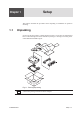
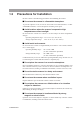
■
Installation of tw
o or more scanner
s
The scanner may be placed on the
T
OS9200/9201 tester
. Ho
we
v
er
, to ensure
safety
, only one scanner should be stack
ed on the tester
.
When tw
o or more scanners are used, mount them on a rack or install (an)
additional scanner(s) ne
xt to the tester proper
. Moreo
v
er
, no more than tw
o
scanners should be stack
ed on top of each other
.
Fig.1-3
Installation of
T
w
o Scanners
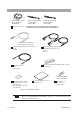
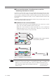
•
The cable supplied with the product is not long enough to connect the scanner
located ne
xt to the tester proper
.
An optional longer cable is a
v
ailable from
Kikusui. If you need this cable, please contact your Kikusui distrib
utor/agent.
TL04-T
OS high-v
oltage leads for parallel connection,
1.5 m [KA-0612-01]
Interf
ace cable,
2 m [85-50-0140]
The stackin
g
of two or more scanners
o
n t
h
e tester is
p
ro
h
i
b
ite
d
.
NOTE