Part No. Z1-002-432, IB002858 Sep. 2009 OPERATION MANUAL HIGH-VOLTAGE SCANNER TOS9200 Series TOS9220 TOS9221 DANGER This Tester generates high voltage. Any incorrect handling may cause death. Read Chapter 2 “PRECAUTIONS ON HANDLING” in this manual to prevent accident. Keep this manual together with the manual for TOS9200/9201, near the tester for easy access of the operator.
Use of Operation Manual Please read through and understand this Operation Manual before operating the product. After reading, always keep the manual nearby so that you may refer to it as needed. When moving the product to another location, be sure to bring the manual as well. If you find any incorrectly arranged or missing pages in this manual, they will be replaced. If the manual gets lost or soiled, a new copy can be provided for a fee.
To supervisor in charge of operation • If the operator does not read the language used in this manual, translate the manual into appropriate language. • Help the operator in understanding this manual before operation. • Keep this manual together with the manual for TOS9200/9201, near the tester for easy access of the operator.
Power Requirements of this Product Power requirements of this product have been changed and the relevant sections of the Operation Manual should be revised accordingly. (Revision should be applied to items indicated by a check mark ✓.) Input voltage The input voltage of this product is and the voltage range is to VAC, VAC. Use the product within this range only. Input fuse The rating of this product's input fuse is A, VAC, and .
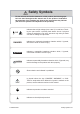
Safety Symbols For the safe use and safe maintenance of this product, the following symbols are used throughout this manual and on the product. Understand the meanings of the symbols and obser ve the instructions they indicate (the choice of symbols used depends on the products). OR Indicates that a high voltage (over 1 000 V) is used here. Touching the part causes a possibly fatal electric shock.
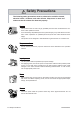
Safety Precautions The following safety precautions must be observed to avoid fire hazard, electrical shock, accidents, and other failures. Keep them in mind and make sure that all of them are observed properly. Users • This product must be used only by qualified personnel who understand the contents of this operation manual. • If it is handled by disqualified personnel, personal injury may result. Be sure to handle it under supervision of qualified personnel (those who have electrical knowledge.
Installation • When installing products be sure to observe "Precautions for Installation" described in this manual. • To avoid electrical shock, connect the protective ground terminal to electrical ground (safety ground). • When installing products with casters, be sure to lock the casters. Relocation • Turn off the power switch and then disconnect all cables when relocating the product. • Use two or more persons when relocating the product which weights more than 20 kg.
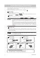
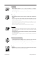
Front panel and Rear panel • Before using the tester, be sure to read Chapter2 "Precautions on Handling". Lighted lamp means that the scanner is in “DANGER HIGH VOLTAGE” state. TOS9220/9221 Danger HIGH VOLTAGE terminals TOS9220 To ensure safety, be sure to connect to an earth ground. See “1.5 Grounding”. Danger HIGH VOLTAGE terminals TOS9221 To ensure safety, be sure to connect to an earth ground. See “1.5 Grounding”.
Description of Contents This manual is composed of the following chapters: Preface This section provides an outline of the scanner and explains its features Chapter 1 Setup This chapter describes the procedures from unpacking to installation to operation checking. Chapter 2 Precautions on Handling This chapter describes the precautions to be followed in the handling of this scanner. When using the scanner, take utmost care to ensure safety.
Contents Safety Symbols - - - - - - - - - - - - - - - - - - - - - - - - - - - - - - - - - - - - - - - - - - - - - - - - III Safety Precautions - - - - - - - - - - - - - - - - - - - - - - - - - - - - - - - - - - - - - - - - - - - - - - IV Description of Contents - - - - - - - - - - - - - - - - - - - - - - - - - - - - - - - - - - - - - - - - - VII Preface About This Manual - - - - - - - - - - - - - - - - - - - - - - - - - - - - - - - - - - - - - - - - - - - P-1 Outline and Features - - - - - - - - - - - - -
Chapter 6 Specifications Electrical performance - - - - - - - - - - - - - - - - - - - - - - - - - - - - - - - - - - - - - - - - - - 6-1 General Specifications - - - - - - - - - - - - - - - - - - - - - - - - - - - - - - - - - - - - - - - - - - 6-3 Dimensions - - - - - - - - - - - - - - - - - - - - - - - - - - - - - - - - - - - - - - - - - - - - - - - - - 6-4 Index- - - - - - - - - - - - - - - - - - - - - - - - - - - - - - - - - - - - - - - - - - - - - - - - - - - - - - - I-1 TOS9200/9221 Contents IX
X Contents TOS9200/9221
Preface About This Manual This Operation Manual is for the TOS9220 and TOS9221 high-voltage scanners. In this manual, the TOS9220 or TOS9221 high-voltage scanner is referred to as the “TOS9220/9221 scanner” or simply the “scanner,” while the TOS9200 or TOS9201 withstanding voltage/insulation resistance tester is referred to as the “TOS9200/ 9201 tester” or the “tester proper.” Moreover, the combination of the TOS9200/9201 tester and TOS9220/9221 scanner is referred to as a “test system.
P-2 Preface TOS9220/9221
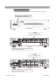
Setup Chapter 1 This chapter describes the procedures from unpacking to installation to operation checking. 1.1 Unpacking Upon receiving the product, confirm that the necessary accessories are included and have not been damaged in transit. Should any damage or shortage be found, please contact Kikusui distributor/agent. Fig.1-1 Packing/Unpacking NOTE TOS9220/9221 • Retain the packing material for future transport.
or or Rated voltage: 125 Vac PLUG: NEMA5-15 [85-AA-0003] AC power cord (1 pc.) Rated voltage: 250 Vac PLUG: CEE7/7 [85-AA-0005] Rated voltage: 250 Vac PLUG: GB1002 [85-10-0790] The power cord that is provided varies depending on the destination for the product at the factory-shipment. Four leadwires for TOS9220 Eight leadwires for TOS9221 TL07-TOS high-voltage test leadwires, red 1.5 m [84180] TL06-TOS high-voltage leadwires for parallel connections (1 set) 0.5 m [84170] Interface cable (1 pc.) 0.
1.2 Precautions for Installation Be sure to observe the following precautions when installing the scanner. ■ Do not use the scanner in a flammable atmosphere. To prevent explosion or fire, do not use the scanner near alcohol, thinner, or other combustible materials, or in an atmosphere containing such vapors. ■ Avoid locations where the scanner is exposed to high temperatures or direct sunlight. Do not locate the scanner near a heater or in areas subject to drastic temperature changes.
■ Do not use the scanner in locations near a sensitive measuring instrument or receiver. Operation in a location subject, may cause such equipment may be affected by noise generated by the scanner. At a test voltage exceeding 3 kV, corona discharge may be gener- ated to produce substantial amounts of RF broadband emissions between grips on the test leadwire. To minimize this effect, secure a sufficient distance between alligator clips.
■ Secure adequate space around the power plug. Do not insert the power plug to an outlet where accessibility to the plug is poor. And, do not place objects near the outlet that would result in poor accessibility to the plug. 1.3 Precautions for Moving When moving the scanner to the installation site or otherwise transporting it, take the following precautions: ■ When moving the scanner, Disconnect all wires from it.
1.4 Connecting the AC Power Cord The power cord that is provided varies depending on the destination for the product at the factory-shipment. WARNING • This instrument is designed to operate from the over voltage categor y II. Do not operate it from the over voltage categor y III or IV. • The AC power cord for 100 V system shown in Fig. 1-4 has a rated voltage of 125 VAC. If this AC power cord is used at the line voltage of a 200 V system, replace the AC power cord with that satisfying that line voltage.
1.5 Grounding WARNING • Be sure to connect the scanner to an electrical ground (safety ground). If the output to a conveyor or peripheral device that is connected to an earth ground or a nearby commercial power line is short-circuited without grounding, the scanner chassis is charged to an excessively high voltage, resulting in extreme danger. • This scanner is designed as a Class I equipment (equipment protected against electric shock with protective grounding in addition to basic insulation).
1-8 Setup TOS9220/9221
Chapter 2 Precautions on Handling This chapter describes the precautions to be followed in the handling of this scanner. When using the scanner, take utmost care to ensure safety. WARNING • The scanner derivers a 5 kVAC/6 kVDC test voltage from the tester proper. The voltage can cause human injury or death. When operating the scanner, be extremely careful and observe the cautions, warnings, and other instructions given in this chapter. 2.
2.2 Action When in Emergency In case of an emergency (such as electric shock hazard or burning of DUT), take the following actions. You may do either (a) or (b) first. But be sure to do both. (a)Turn OFF the power switch of the tester proper. (b)Disconnect the AC power cord of the tester proper from the AC line receptacle. Finally, disconnect the AC power cord of the scanner from the AC line receptacle. 2.
WARNING • The vinyl sheaths of the alligator clips of the test leadwires which are sup- plied accompanying the scanner have no sufficient insulation for the high test voltages. Never touch them when in test. Alligator clip Never touch this part. Fig.2-2 Supplied test leadwire ■ Matters to be Sure of After Turning-OFF Power If you have to touch the DUT, test leadwires, probes, and/or output terminals and their vicinities for re-connections or other reasons, be sure of the following two matters.
2.4 Daily Checking To avoid accidents, confirm at least the following before starting operation. Common items for both the TOS9220 and TOS9221 scanners • The scanner and tester is connected to an ear th ground. • The coating of the high-voltage test leadwire is free from cracks, fissures, and breakage. • The high-voltage test leadwire is not broken.
Connections Chapter 3 This chapter describes the connections between the scanner, TOS9200/9201 tester, and DUT. For information on operations such as setting the scanner output after all connections have been made, see the Operation Manual for the TOS9200/9201 Testers. NOTE 3.1 • This scanner is a dedicated option for the TOS9200 and TOS9201 withstanding voltage/insulation resistance testers. It cannot be connected to other testers.
■ Channel Assignment The TOS9200/9201 tester assigns channel numbers to the TOS9220/9221 scanners, treating the scanner directly connected to the tester proper via the interface cable as the first one, followed by that next closest to the tester proper, and so on. See Fig. 31. Table 3-1 specifies the correspondence between channels viewed from the tester proper and the channels of each scanner when the scanners are connected to the TOS9200/9201 tester.
Procedure for connecting the scanners to the TOS9200/9201 tester The following provides an example involving the connection of three TOS9220/ 9221 scanners to the TOS9200/9201 tester. See Fig. 3-1 and Table 3-2. NOTE • When connecting four TOS9220/9221 scanners, connect the 4th scanner to the 3rd scanner in the same way as the 1st and 2nd scanners and the 2nd and 3rd scanners in Fig. 3-1. 1. Turn OFF the POWER switch of the tester proper. 2.
Cable 8 1st TOS9220/9221 Cable 5 3rd TOS9220/9221 Cable 1 Cable 9 Cable 7 Cable 3 Cable 4 Cable 6 2nd TOS9220/9221 TOS9200/9201 Cable 2 Fig.3-1 Connection of Three Scanners to the Tester Proper Table3-2 Cable No.
Use the fixing metal to securely fasten leads in order to prevent disconnection. Fig.3-2 Connection to the LOW Terminal 1. With the cable clamper raised, connect the high-voltage leads for parallel connection to the terminals. Cable clamper 2. Put the cable clamper back in place. Locked Fig.
3.2 Connecting the TOS9220 Scanner to the DUT Prior to connection The following describes important points that must be understood, such as the operation of the TOS9220 scanner, before connecting it to the DUT. ■ Operation of the TOS9220 Scanner The state in which all four-channel outputs of the TOS9220 scanner are connected to the test points of the DUT is shown in Fig. 3-4.
RL 1a CH1 output terminal Test point A RL 1b RL 2a CH2 output terminal Test point B RL 2b RL 3a CH3 output terminal Test point C RL 3b RL 4a CH4 output terminal Test point D RL 4b OUT HIGH VOLTAGE terminal OUT LOW terminal DUT IN HIGH VOLTAGE terminal IN LOW terminal SCANNER OUT terminal Control circuit TOS9220 SCANNER IN terminal SCAN terminal HIGH VOLTAGE terminal LOW terminal TOS9200/9201 Fig.
RL 1a CH1 output terminal Test point A RL 1b RL 2a CH2 output terminal Test point B RL 2b RL 3a CH3 output terminal Test point C RL 3b RL 4a CH4 output terminal Test point D RL 4b OUT HIGH VOLTAGE terminal DUT OUT LOW terminal Chassis IN HIGH VOLTAGE terminal IN LOW terminal SCANNER OUT terminal Control circuit TOS9220 SCANNER IN terminal SCAN terminal HIGH VOLTAGE terminal LOW terminal TOS9200/9201 Fig.
■ Reducing the effects of noise If a short circuit or breakdown occur, noise generated can lead to the malfunctioning of peripheral electronic components. To reduce the effects of noise, install a toroidal core or a resistor of approximately 470 Ω between the DUT and the end of the highvoltage test leadwire from the scanner, and between the DUT and the end of the low-voltage test leadwire, as close as possible to the DUT. See Fig. 3-6.
Procedure for connecting the scanner to the DUT 1. Turn OFF the POWER switch of the tester proper. 2. Confirm that the analog voltmeter on the tester proper reads “0.” 3. Before making connections, check that the test leadwires in use do not contain broken wires and that the coating is not damaged. 4. Connect the test leadwires to the output ter minals of the channels to be used for a test. The connection to the output terminals is the same as that to the IN HIGH VOLTAGE terminal. See Fig. 3-3. 5.
3.3 Connecting the TOS9221 Scanner to the DUT The following describes important points that must be understood, such as the operation of the TOS9221 scanner, before connecting it to the DUT. ■ Operation of the TOS9221 Scanner The state of the connections of all four channel outputs of the TOS9221 scanner to the test points of the DUT is shown in Fig. 3-7.
RL 1a CH1 A output terminal RL 1b CH1 B output terminal RL 2a CH2 A output terminal RL 2b CH2 B output terminal RL 3a CH3 A output terminal RL 3b CH3 B output terminal RL 4a CH4 A output terminal RL 4b CH4 B output terminal Test point A Test point B Test point C Test point D OUT HIGH VOLTAGE terminal OUT LOW terminal DUT IN HIGH VOLTAGE terminal IN LOW terminal SCANNER OUT terminal Control circuit TOS9221 SCANNER IN terminal SCAN terminal HIGH VOLTAGE terminal LOW terminal TOS9200
high-voltage digital voltmeter or the TOS1200 current calibrator, to the scanner. Otherwise, the ammeter will be short-circuited. For more information, see “Setting LOW/GUARD for the GND” in Chapter 3 “Basic Operations” of the Operation Manual for the TOS9200/9201 Testers. RL 1a CH1 A output terminal RL 1b CH1 B output terminal Test point A Relay on TOS9221 DUT Fig.3-8 Connection Failure Procedure for connecting the scanner to the DUT 1. Turn OFF the POWER switch of the tester proper. 2.
NOTE 3-14 Connections • The test voltage applied to channels set to HIGH leaks into the output terminals of a channel that has been set to OPEN on the tester proper through stray capacitances within the scanner. Moreover, if test leadwires have been connected to a channel set to OPEN, the voltage also leaks to its output terminals through stray capacitance between the test leadwires.
Chapter 4 Part Names and Functions This chapter describes the names and functions of components such as switches, displays, and connectors on the front and rear panels. 4.1 Front Panel [2] [1] [3] Fig.4-1 Front Panel (The figure shows model TOS9220.) [1] DANGER This red lamp indicates that a high voltage is being output.
4.2 [4] [13] [14] Rear Panel [5] [9] [11] [10] [12] [7] [9] [11] [8] [10] [12] [6] [15] Fig.4-2 TOS9220 Rear Panel [4] [13] [14] [5] [15] Fig.4-3 TOS9221 Rear Panel [4] SCANNER IN This connector connects to the SCAN connector of the TOS9200/9201 tester. When multiple scanners are connected in parallel, it connects to the SCANNER OUT connector of another TOS9220/9221 scanner.
[7] OUTPUT A (TOS9221 only) The A-output terminal of each channel is an output terminal on the high-voltage side (HIGH VOLTAGE). The A-output terminal of a channel set to HIGH on the TOS9200/9201 tester is connected to the high-voltage side (HIGH VOLTAGE potential) of the test voltage. The A-output terminal of a channel not set to HIGH is in the open state (not connected to another point).
[13] Protective conductor terminal This terminal is used to ground the scanner. WARNING • Always ground the scanner. For more information, see “1.5 Grounding.” [14] AC LINE This is the connector for the AC power cord that supplies power to the scanner. WARNING • Improper handling of the AC LINE connector may result in electric shock. Be sure to follow the instructions in "1.4 Connecting the AC Power Cord". • To ensure safety, be sure to ground the scanner. For more information, see “1.5 Grounding.
Maintenance Chapter 5 This chapter describes the maintenance, inspection, and calibration of the scanner. Regular maintenance and inspection are necessary to maintain the initial performance of the product. 5.1 Cleaning To clean the surface of the tester, including the panel, wipe it with a soft cloth moistened with water-diluted neutral detergent. WARNING • Before starting cleaning, be sure to turn off the POWER switch of the tester proper and unplug the scanner’s AC power cord.
5.3 Replacing the Fuse WARNING • To prevent electric shock, before checking or replacing the fuse, be sure to turn off the POWER switch of the tester proper and unplug the scanner’s AC power cord. • Make sure that the fuse used conforms to the instrument specifications, including shape, rating, and characteristics. Using a fuse with different rating or shor t-circuiting, the fuse holder will damage the instr ument. 1.
5.4 Maintenance WARNING • The TOS9220/9221 scanner handles voltages as high as 5 kV AC/6 kV DC. Since maintenance of the scanner, such as an overhaul, involves considerable risk, all maintenance should be performed by our service personnel. ■ High-voltage relays The high-voltage relays inside the scanner are consumables. Although service life depends on the usage environment, we recommend that the high-voltage relays be replaced every one million withstanding voltage tests.
Symptom2: The POWER ON LED is lit, but the scanner does not function. Possible cause The SCAN terminal of the tester proper is connected to the SCANNER OUT terminal of the scanner. A channel not configured on the TOS9200/9201 tester is being used. • • Remedy The interface cable is not connected correctly. Connect it correctly by referring to "3.1 Connecting the Scanner to the TOS9200/9201 Tester". Channels connected to test points must be set on the tester proper.
Specifications Chapter 6 This chapter describes the electrical and mechanical specifications for the scanner. Electrical performance Item Maximum rating voltage TOS9220 AC 5.0 kV DC 6.0 kV TOS9221 Number of channels 4 (Each channel is settable to HIGH, LOW, or OPEN.) Maximum number of scanners connected 4 scanners Channel numbers are determined in order of connection to the TOS9200/9201 tester.
Item TOS9220 TOS9221 Safety*2, *3 Conforms to the requirements of the following directive and standard. Low Voltage Directive 2006/95/EC EN61010-1 Class I Pollution degree 2 Electromagnetic compatibility (EMC)*2 Conforms to the requirements of the following directive and standard. EMC Directive 2004/108/EC EN61326-1 EN61000-3-2 EN61000-3-3 Under following conditions 1. Used test leadwire TL07-TOS which is supplied. 2. No discharge occurs at outside of the tester. 3.
General Specifications Item Environment TOS9220 Installation location Indoors and at altitudes up to 2 000 m Warranty range Temperature 5 ˚C to 35 ˚C (41 °F to 95 °F) Humidity 20 % to 80 % RH (no condensation) Operating range Temperature 0 ˚C to 40 ˚C (32 °F to 104 °F) Humidity 20 % to 80 % RH (no condensation) Storage range Temperature Humidity -20 ˚C to 70 ˚C (-4 °F to 158 °F) 90 % RH or less (no condensation) Dimensions See Fig. 6-1 Dimensions. Weight Approx. 6.5 kg (14.
370 (14.57) 88 (3.46) MAX105 (4.13) MAX5 (0.20) MAX415 (16.33) Dimensions MAX435 (17.13) 430 (16.93) Unit: mm (inch) Fig.
Index A M AC LINE 4-4 AC power cord 1-6 accessories 1-2 alligator clips 2-3 maintenance 5-3 Moving 1-5 C CHANNEL 4-1 channel assignment 3-2 Class I device 1-7 cleaning 5-1 connecting to the DUT TOS9220 scanner 3-6 TOS9221 scanner 3-11 connecting to the tester 3-1 contact check function TOS9220 scanner 3-6 TOS9221 scanner 3-11 D N number of scanners to be connected 3-1 O OUT HIGH VOLTAGE 4-3 OUT LOW 4-3 OUTPUT (TOS9220 only) 4-2 OUTPUT A (TOS9221 only) 4-3 OUTPUT B (TOS9221 only) 4-3 overhaul 5-3 P p