600 USER'S GUIDE for BLOOMFIELD TRADITIONAL DISPLACEMENT-TYPE COFFEE BREWERS Includes: Installation Checkout Theory of Operation Troubleshooting p/n 86772 Rev.
INTRODUCTION The technical content of this manual represents current production models as of October, 2003. Data, specifications and materials, and model number designations are subject to change at any time without notice. This manual is intended for use by qualified service personnel. Bloomfield coffee brewers are intended exclusively for commercial use and are designed expressly to brew beverage products for human consumption. No other use is recommended or authorized by the manufacturer or its agents.
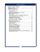
TABLE OF CONTENTS INSTALLATION PROCEDURES …………………………………….. 2 BREWER OVERALL CHECKOUT ……………………………………. 4 BREWING COFFEE …………………………………………………… 5 CLEANING INSTRUCTIONS …………………………………………. 6 THEORY OF OPERATION WATER FLOW ………………………………………...………….… 7 HOT WATER FAUCET …………………………………………….. 8 BREW WATER TEMPERATURE CONTROL …………………… 9 TROUBLESHOOTING GUIDE QUICK GUIDE ………………………………………………………. 10 BREW WATER SYSTEM - AUTOMATIC OPERATION .....…… 11 BREW WATER SYSTEM - POUR-OVER ………………………..
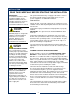
INSTALLATION READ THIS CAREFULLY BEFORE STARTING THE INSTALLATION IMPORTANT: To enable the installer to make a quality installation and to minimize installation time, the following suggestions and tests should be done before the actual unit installation is started: CAUTION: ELECTRICAL DAMAGE DO NOT plug in or energize this appliance until all Installation Instructions are read and followed. Damage to the Brewer will occur if these instructions are not followed.
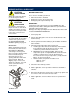
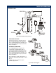
INSTALLATION (continued) NSF requires that the brewer be able to be moved for cleaning underneath. A flex line or loops of copper tubing will satisfy this requirement. See Figure 2 below. NOTE: This equipment must be installed to comply with applicable federal, state and local plumbing codes and ordinances. WARNING: SHOCK HAZARD Water Supply Installation In some areas, local codes require a backflow preventer (check valve) to be installed on the inlet water line.
BREWER OVERALL CHECK-OUT CAUTION: SHOCK HAZARD Always disconnect the brewer fro electrical power before servicing or cleaning. CAUTION: BURN HAZARD Brew water is extremely hot. Exposed surfaces of the brew chamber and airpot ,decanter or thermal server may be HOT to the touch, and can cause serious burns.
BREWING COFFEE CAUTION: Burn Hazard PREPARATION Place one (1) genuine Bloomfield paper filter in the brew chamber. Add a pre-measured amount of fresh coffee grounds. Gently shake the brew chamber to level the bed of grounds. Slide the brew chamber into place under the brew head. Brew Chamber PAPER FILTER BREW CHAMBER POUR-OVER OPERATION BE sure “READY TO BREW” light is lit. Place the appropriate EMPTY decanter in place under the brew chamber. Fill a decanter with tap water.
CLEANING INSTRUCTIONS CAUTION: PROCEDURE: Clean Coffee Brewer BURN HAZARD Brewing and serving temperatures of coffee are extremely hot. Hot coffee will cause serious skin burns. PRECAUTIONS: Disconnect brewer from electric power. Allow brewer to cool. FREQUENCY: Daily TOOLS: Mild Detergent, Clean Soft Cloth or Sponge Bristle Brush, Bottle Brush CAUTION: SHOCK HAZARD Do not submerge or immerse brewer in water.
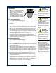
THEORY OF OPERATION WATER FLOW Typical Brew Water Delivery System POUR-OVER FEATURE Pouring any amount of cold water into the pour-over opening and into the basin pan forces an identical amount of hot water out of the tank and through the spray head into the brew chamber. AUTOMATIC OPERATION Pressing BREW button energizes the solenoid valve, allowing water from an external water supply to flow into the basin pan and then into the hot water tank.
THEORY OF OPERATION (continued) HOT WATER FAUCET Typical Hot Water Faucet System The faucet water coil is submerged in the hot water tank and draws heat from the brew water. Faucet water flows through the bypass side of the water inlet and is not controlled by the solenoid valve. The faucet is at supply water pressure any time the faucet shut-off valve is OPEN.
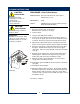
THEORY OF OPERATION (continued) BREW WATER TEMPERATURE CONTROL Typical Heating System Electrical Configuration The heating elements are energized when line power is applied to the element terminals. Water temperature is sensed by a thermobulb inserted into the water tank. This temperature signal is fed to the thermostat by a capillary tube. An increase in temperature causes an increase in pressure in the thermobulb. This will cause the pressure diaphragm in the thermostat to open the line power contacts.
TROUBLESHOOTING GUIDE QUICK GUIDE SYSTEM The first step in troubleshooting is to determine where to start. A few simple checks should quickly point to the major area of concern. BREW WATER - AUTOMATIC OPERATION .....……..… BREW WATER - POUR-OVER ………………………..….. FAUCET WATER ………………………………….……….. ELECTRICAL - BREW ……………………………….……. ELECTRICAL - HEATING ……………………………….… ELECTRICAL - WARMERS ………………………….….….
TROUBLESHOOTING GUIDE (continued) BREW WATER SYSTEM - AUTOMATIC OPERATION 11
TROUBLESHOOTING GUIDE (continued) BREW WATER SYSTEM - AUTOMATIC OPERATION 12
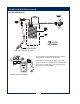
TROUBLESHOOTING GUIDE (continued) BREW WATER SYSTEM - AUTOMATIC IMPORTANT: To avoid overflowing the brew container, ALWAYS start the brew with an empty container under the brew head.
TROUBLESHOOTING GUIDE (continued) BREW WATER SYSTEM - AUTOMATIC OR POUR-OVER OPERATION 14
TROUBLESHOOTING GUIDE (continued) BREW WATER SYSTEM - POUR-OVER OPERATION 15
TROUBLESHOOTING GUIDE (continued) FAUCET WATER SYSTEM 16
TROUBLESHOOTING GUIDE (continued) FAUCET WATER SYSTEM 17
TROUBLESHOOTING GUIDE (continued) FAUCET WATER SYSTEM 18
TROUBLESHOOTING GUIDE (continued) ELECTRICAL SYSTEM - BREW CAUTION: ELECTRIC SHOCK HAZARD Exposed electric circuits. Use due caution when working near live electric circuits.
TROUBLESHOOTING GUIDE (continued) ELECTRICAL SYSTEM - HEATING CAUTION: ELECTRIC SHOCK HAZARD Exposed electric circuits. Use due caution when working near live electric circuits.
TROUBLESHOOTING GUIDE (continued) CAUTION: ELECTRIC SHOCK HAZARD Exposed electric circuits. Use due caution when working near live electric circuits.
SERVICING INSTRUCTIONS CAUTION Electric Shock Hazard These procedures involve exposed electrical circuits. These procedures are to be performed by qualified technical personnel only. TEMPERATURE ADJUSTMENT Unplug power cord or turn circuit breaker OFF. Remove top panel. Pull vent tube out of tank lid and insert a thermometer of known accuracy in vent hole. Reconnect brewer to electrical power. Fig.
SERVICING INSTRUCTIONS (continued) TIMER ADJUSTMENT The amount of water dispensed automatically during a brew cycle is controlled by the timer. Place empty decanter under brew chamber. Press BREW button. Brewer should dispense one decanter of water. To adjust amount: Remove brew chamber and button plug. Adjust knob on timer; clockwise increases time. Run several cycles to check amount of water delivered. Replace button plug. IMPORTANT: Water pressure must be between 20 p.s.i and 90 p.s.i. flowing pressure.
SERVICING INSTRUCTIONS (continued) REPLACE SOLENOID Symptom: Automatic brewer will not flow water; or, automatic brewer drips continuously from brew head. Unplug power cord or turn circuit breaker OFF. Turn OFF and disconnect water supply from brewer inlet fitting. Unscrew water inlet fitting from solenoid. Remove two screws holding access door in place. Remove two screws holding solenoid to door. Disconnect wiring from solenoid.
SERVICING INSTRUCTIONS (continued) REPLACE TIMER ASSEMBLY Unplug power cord or turn circuit breaker OFF. Remove front panel. Remove knob and three screws holding timer to bracket. Disconnect wiring to timer. IMPORTANT: When replacing water faucet coil, also replace seal gaskets. Reassemble in reverse order. Adjust timer as described on page 13 REPLACE HOT WATER FAUCET COIL Symptom: Brewer drips continuously from brew head, except when faucet valve is turned OFF. Remove tank lid assembly per above.
SERVICING INSTRUCTIONS (continued) CAUTION CHEMICAL BURN HAZARD Deliming chemicals are caustic. Wear appropriate protective gloves and goggles during this procedure. Never siphon deliming chemicals or solutions by mouth. This operation should only be performed by qualified and experienced service personnel. IMPORTANT: DO NOT spill, splash or pour water or deliming solution into or over any internal component other than the inside of the water tank.
SERVICING INSTRUCTIONS (continued) 7. Set the tank back into the brewer. Reassemble the tank lid to the water tank. Make sure the gasket is properly in place, then reinstall the hold-down strap. 8. Reinstall wiring to heating element and thermostat. Reinstall the hi-limit thermostat (if removed). For brewers with hot water faucet, reassemble faucet piping. Verify that all internal components are dry, then reinstall the top panel. 10.
Bloomfield Industries proudly supports CFESA Commercial Food Equipment Service Association Bloomfield Industries, Inc. Division of Carrier Commercial Refrigeration In US and Canada Telephone: 775-689-5700 Fax: 888-492-2783 Fax: 800-356-5142 (for orders only) website: www.wellsbloomfield.