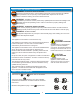
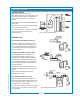
603 BLOOMFIELD INDUSTRIES 10 Sunnen Drive St. Louis, MO 63143 telephone: 314-678-6336 fax: 314-781-2714 www.wellsbloomfield.com Model 8774 Brewer with optional 8881 Airpot OWNERS MANUAL For INTEGRITY™ COFFEE BREWERS MODELS 8773 Automatic Airpot Brewer 8774 Pour-Over Airpot Brewer Domestic and Export Models Includes: Model 8773 Brewer with optional 8881 Airpot p/n 2M-76451 Rev.
WARRANTY STATEMENT It also does not apply if the serial nameplate has been removed or unauthorized service personnel perform service. The prices charged by Bloomfield Industries for its products are based upon the limitations in this warranty. Seller’s obligation under this warranty is limited to the repair of defects without charge by a Bloomfield Authorized Service Agency or one of its sub-agencies. This service will be provided on customer’s premises for non-portable models.
TABLE OF CONTENTS WARRANTY STATEMENT SPECIFICATIONS FEATURES & OPERATING CONTROLS PRECAUTIONS & GENERAL INFORMATION AGENCY LISTING INFORMATION INSTALLATION INSTRUCTIONS OPERATION BREWING COFFEE CLEANING INSTRUCTIONS TROUBLESHOOTING SUGGESTIONS SERVICING INSTRUCTIONS Deliming Instructions EXPLODED VIEWS & PARTS LISTS SERVICE KITS WIRING DIAGRAMS xi 1 2 3 3 4 6 8 9 10 11 16 18 22 23 Thank You for purchasing this Wells Bloomfield appliance.
IL1626 Fig.
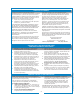
PRECAUTIONS AND GENERAL INFORMATION WARNING: Electric Shock Hazard All servicing requiring access to non-insulated components must be performed by qualified service personnel. Do not open any access panels which require the use of tools. Failure to heed this warning can result in electrical shock. WARNING: Injury Hazard All installation procedures must be performed by qualified personnel with full knowledge of all applicable electrical and plumbing codes.
INSTALLATION INSTRUCTIONS READ THIS CAREFULLY BEFORE STARTING THE INSTALLATION Equipment Damage DO NOT plug in or energize this appliance until all Installation Instructions are read and followed. Damage to the Brewer will occur if these instructions are not followed. CAUTION: Unstable Equipment Hazard It is very important for safety and for proper operation that the brewer is level and stable when standing in its final operating position.
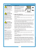
INSTALLATION INSTRUCTIONS (continued) WARNING: SHOCK HAZARD IL1596 Fig. 2 Water Supply Installation - New-Style Brewers In some areas, local codes require a backflow preventer (check valve) to be installed on the inlet water line. If a backflow preventer is used, you must install a water hammer arrester in the incoming line, between the backflow preventer and the brewer inlet, as far away from the brewer as space will allow.
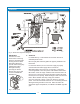
OPERATION IL1627 Fig. 3 Model 8773 Operation Diagram A. START-UP For initial start-up, or if the brewer has not been used for an extended period of time: Be sure spray disk and brew gasket are properly installed in the brew head. For automatic brewers, be sure the water supply is properly connected and the water supply valve is turned ON. BEFORE plugging the brewer into a receptacle, or otherwise connecting brewer to electrical power the water tank must be filled.
OPERATION (continued) WATER HEATER Water temperature is sensed by a thermobulb inserted into the water tank. This temperature signal is fed to the thermostat, which controls line power to the heating element. The setpoint temperature is adjustable at the thermostat. The element is protected from over-temperature by a hi-limit thermostat. To save energy, press the tank heat switch to OFF if no brew is expected for an extended period. Fig.
BREWING COFFEE Burn Hazard Exposed surfaces of the brewer, brew chamber and airpot may be HOT to the touch, and can cause serious burns. CAUTION: Burn Hazard To avoid splashing or overflowing hot liquids, ALWAYS place an empty airpot under the brew chamber before starting the brew cycle. Failure to comply can cause serious burns. CAUTION: Burn Hazard After a brew cycle, brew chamber contents are HOT. Remove the brew chamber and dispose of used grounds with care. Failure to comply can cause serious burns.
CLEANING INSTRUCTIONS PROCEDURE: Clean Coffee Brewer PRECAUTIONS: Disconnect brewer from electric power. Allow brewer to cool. FREQUENCY: Daily TOOLS: Mild Detergent, Clean Soft Cloth or Sponge Bristle Brush, Bottle Brush CAUTION: Burn Hazard Brewing and serving temperatures of coffee are extremely hot. Hot coffee will cause serious skin burns. CAUTION: 1. Disconnect brewer from electric power. Allow brewer to cool before cleaning. Shock Hazard Do not submerge or immerse brewer in water. 2.
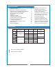
TROUBLESHOOTING SUGGESTIONS Water won’t heat (be sure TANK HEAT switch is ON) Coffee level low (pour-over) Coffee level too high or low (automatic) Brew chamber overflows Sprays water from brew head No brew (automatic) No flow from hot water faucet Poor coffee quality POSSIBLE CAUSE SUGGESTED REMEDY Brewer unplugged or circuit breaker tripped Check power supply cord Check / reset circuit breaker Thermostat set too low Set for desired temperature Hi-Limit thermostat tripped Allow to cool, Reset
SERVICING INSTRUCTIONS ACCESS PANELS CAUTION: TOP PANEL: Remove top panel to access hot water tank, thermostat, heating elements, brew circuit tubing, faucet valve and piping. Top panel is held by two screws at the rear and a retaining lip at the front. FRONT PANEL: Remove front panel to access timer . Front panel is held by a screws through the bottom panel and a retaining lip at the top.
SERVICING INSTRUCTIONS (continued) TEMPERATURE ADJUSTMENT CAUTION: SHOCK HAZARD Unplug power cord or turn circuit breaker OFF. Remove top panel. These procedures involve exposed electrical circuits. These procedures are to be performed by qualified technical personnel only. Pull vent tube out of tank lid and insert a thermometer of known accuracy in vent hole. Reconnect brewer to electrical power. NOTE: Optimum brewing temperature range is 195ºF to 205ºF (90ºC to 96ºC).
SERVICING INSTRUCTIONS (continued) TIMER ADJUSTMENT (AUTOMATIC BREWERS ONLY) The amount of water dispensed automatically during a brew cycle is controlled by the timer. Place empty decanter under brew chamber. Press BREW button. Brewer should dispense one decanter of water. To adjust amount: Remove brew chamber and button plug. Adjust knob on timer; clockwise increases time. Run several cycles to check amount of water delivered. Replace button plug. IMPORTANT: Water pressure must be between 20 p.s.
SERVICING INSTRUCTIONS (continued) IMPORTANT: When replacing heating element, also replace seal gaskets. REPLACE HEATING ELEMENT Remove tank lid assembly per above. Remove two hex nuts holding element to cover. Pull element from mounting holes. Reassemble in reverse order. REPLACE SOLENOID Symptom: Automatic brewer will not flow water; or, automatic brewer drips continuously from brew head. NOTE: Wrench p/n 86660 is designed to allow easy removal of the hoses from the plastic solenoid valve.
SERVICING INSTRUCTIONS (continued) REPLACE TIMER ASSEMBLY Unplug power cord or turn circuit breaker OFF. Remove front panel. Remove knob and three screws holding timer to bracket. Disconnect wiring to timer. Reassemble in reverse order. Adjust timer as described on page 13 REPLACE HOT WATER FAUCET COIL Symptom: Brewer drips continuously from brew head, except when faucet valve is turned OFF. Remove tank lid assembly per above. IMPORTANT: When replacing water faucet coil, also replace seal gaskets.
SERVICING INSTRUCTIONS (continued) CHEMICAL BURN HAZARD Deliming chemicals may be caustic. Wear appropriate protective gloves and goggles during this procedure. Never siphon deliming chemicals or solutions by mouth. PROCEDURE: Delime the Water Tank PRECAUTIONS: Disconnect brewer from electric power. Allow brewer to cool.
SERVICING INSTRUCTIONS (continued) 7. Set the tank back into the brewer. Reassemble the tank lid to the water tank. Make sure the gasket is properly in place, then reinstall the hold-down strap. 8. Reinstall wiring to heating element and thermostat. Reinstall the hi-limit thermostat (if removed). For automatic brewers, reassemble piping for the faucet. Verify that all internal components are dry, then reinstall the top panel. 9.
EXPLODED VIEW & PARTS LIST HOT WATER TANK ASSEMBLY IL1630 ITEM PART NO. 13 2C-70134 HOLD-DOWN STRAP 8773, 8774 2C-73457 NUT, HEX 8-32 KEPS 8773, 8774 50 WS-8512-51 THERMOSTAT (BLACK BODY - INCL. SEAL & MOUNTING SCREWS) WS-86280 THERMO (ALT) (GRAY BODY - INCL.
EXPLODED VIEW & PARTS LIST (continued) CABINET PLUMBING COMPONENTS IL1631 ITEM PART NO.
EXPLODED VIEW & PARTS LIST (continued) ELECTRICAL COMPONENTS IL1632 ITEM PART NO.
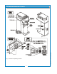
EXPLODED VIEW & PARTS LIST (continued) CABINET COMPONENTS IL1633a ITEM DESCRIPTION USED ON 33 2I-70139 GASKET, SPRAY HEAD 8773, 8774 34 A6-72727 SPRAY DISK, EMBOSSED 8773, 8774 34a A6-70163 RETAINER, SPRAY HEAD (REQUIRES DRILL/RIVETS TO INSTALL) 8773, 8774 70 2P-70053 BUTTON PLUG, 2”, METAL 8773, 8774 73 2A-71732 LEG ASSEMBLY, LEVELLING 8773, 8774 2K-70229 BUSHING, HEYCO (LARGE) 2K-41928 BUSHING, HEYCO (SMALL) 77 2P-70272 BUTTON PLUG 8774 104 2Q-75089 DOOR, SOLENOID ACCESS
SERVICE KITS SOLENOID REPAIR KITS WS-85218 WS-85219 Inlet Fitting Kit (items 45a, 45b, 45c, 45d) Inlet Strainer (item 45d) IL1612 COMPLETE SPARE TANK COVER WS-8541 WF-300 Spare Cover Assembly (120V, 1500W, 8773 (U.S. & Canada) With Coil - all parts mounted to cover) WS-8543-300 Spare Cover Assembly (120V, 1500W, 8774 (U.S.
603 p/n 76451 8773_8774 Owmers Manual WIRING DIAGRAMS 23
WIRING DIAGRAMS (continued) 24 603 p/n 76451 8773_8774 Owmers Manual 2M-73651 (-)
603 p/n 76451 8773_8774 Owmers Manual WIRING DIAGRAM (continued) 25
10 Sunnen Drive, St. Louis, MO 63143 telephone: 314-678-6336 fax: 314-781-2714 www.wellsbloomfield.