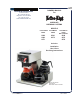
611 OWNERS MANUAL For BLOOMFIELD INDUSTRIES 10 Sunnen Drive St. Louis, MO 63143 telephone: 314-678-6336 fax: 314-781-2714 www.wellsbloomfield.com MODULAR BREWING SYSTEMS MODELS POUR OVER AUTOMATIC UNITS UNITS 8542 8541 8543 8573 8571 AUTOMATIC UNITS WITH FAUCET 8540 8572 8574 Includes: Installation Use & Care Servicing Instructions Model 8574 Brewer with optional 8900-Series Glass Decanters p/n 2M-75804 Rev.
WARRANTY STATEMENT All electrical equipment manufactured by WELLS BLOOMFIELD, LLC is warranted against defects in materials and workmanship for a period of one year from the date of original installation or eighteen (18) months from the date of shipment from our factory, whichever comes first, and is for the benefit of the original purchaser, except that: a. airpots carry a 30 day parts warranty only. b. dispensers; i.e., tea and coffee carry a 90 days parts warranty only, excludes decanters.
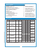
TABLE OF CONTENTS WARRANTY STATEMENT SPECIFICATIONS FEATURES & OPERATING CONTROLS PRECAUTIONS & GENERAL INFORMATION AGENCY APPROVAL INFORMATION INSTALLATION INSTRUCTIONS OPERATION BREWING COFFEE CLEANING INSTRUCTIONS TROUBLESHOOTING SUGGESTIONS SERVICING INSTRUCTIONS Deliming Instructions EXPLODED VIEWS & PARTS LISTS WIRING DIAGRAMS xi 1 2 3 3 4 6 8 9 10 11 16 18 22 Thank You for purchasing this Wells Bloomfield appliance.
IL1695 Fig.
PRECAUTIONS AND GENERAL INFORMATION WARNING: ELECTRIC SHOCK HAZARD WARNING All servicing requiring access to non-insulated components must be performed by qualified service personnel. Do not open any access panels which require the use of tools. Failure to heed this warning can result in electrical shock. WARNING: INJURY HAZARD WARNING WARNING WARNING All installation procedures must be performed by qualified personnel with full knowledge of all applicable electrical and plumbing codes.
INSTALLATION INSTRUCTIONS READ THIS CAREFULLY BEFORE STARTING THE INSTALLATION CAUTION: EQUIPMENT DAMAGE DO NOT plug in or energize this appliance until all Installation Instructions are read and followed. Damage to the Brewer will occur if these instructions are not followed. CAUTION: UNSTABLE EQUIPMENT HAZARD It is very important for safety and for proper operation that the brewer is level and stable when standing in its final operating position.
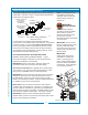
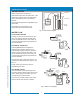
INSTALLATION INSTRUCTIONS (continued) NSF requires that the brewer be able to be moved for cleaning underneath. A flex line or loops of copper tubing will satisfy this requirement. See Figure 2 below. COPPER LOOPS OR FLEX LINES (PROVIDED BY PLUMBER) SOLENOID STRAINER WASHER SHUT-OFF VALVE (PROVIDED BY PLUMBER) WATER SUPPLY WARNING WATER INLET FITTING FLOW Fig.
OPERATION IL1697 Fig. 4 Brewer Operation Diagram A. START-UP For initial start-up, or if the brewer has not been used for an extended period of time: • Be sure spray disk and brew gasket are properly installed in the brew head. • Be sure the water supply is properly connected and the water supply valve is turned ON. • Be sure the WATER TANK IS FILLED BEFORE plugging the brewer into a receptacle, or otherwise connecting brewer to electrical power the water tank must be filled.
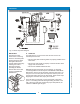
OPERATION (continued) WATER HEATER HI-LIMIT THERMOSTAT Water temperature is sensed by a thermobulb inserted into the water tank. This temperature signal is fed to the thermostat, which controls line power to the heating element. THERMOBULB The setpoint temperature is adjustable at the thermostat. HEATER ELEMENT THERMOSTAT The element is protected from overtemperature by a hi-limit thermostat. Fig.
BREWING COFFEE BURN HAZARD Exposed surfaces of the brewer, brew chamber and decanter may be HOT to the touch, and can cause serious burns. CAUTION: BURN HAZARD To avoid splashing or overflowing hot liquids, ALWAYS place an empty decanter under the brew chamber before starting the brew cycle. Failure to comply can cause serious burns. CAUTION: BURN HAZARD After a brew cycle, brew chamber contents are HOT. Remove the brew chamber and dispose of used grounds with care.
CLEANING INSTRUCTIONS PROCEDURE: Clean Coffee Brewer CAUTION: PRECAUTIONS: Disconnect brewer from electric power. Allow brewer to cool. FREQUENCY: Daily TOOLS: Mild Detergent, Clean Soft Cloth or Sponge Bristle Brush. BURN HAZARD Brewing and serving temperatures of coffee are extremely hot. Hot coffee will cause serious skin burns. CAUTION: SHOCK HAZARD 1. Disconnect brewer from electric power. Do not submerge or immerse brewer in water. Allow brewer to cool before cleaning. 2.
TROUBLESHOOTING SUGGESTIONS Water won’t heat Coffee level low (pour-over) Coffee level too high or low (automatic) Brew chamber overflows Sprays water from brew head No brew (automatic) No flow from hot water faucet Poor coffee quality POSSIBLE CAUSE SUGGESTED REMEDY Brewer unplugged or circuit breaker tripped Check power supply cord Thermostat set too low Set for desired temperature Hi-Limit thermostat tripped Check / reset circuit breaker Allow to cool Reset hi-limit (8786, 8788) Damaged in
SERVICING INSTRUCTIONS ACCESS PANELS Each warmer plate has a center stud which screws into a bracket. Warmer plates on Canadian brewers are secured with a nut. Remove button plug on bottom of brewer to access nut on warmer plate. Remove warmer plates by turning counterclockwise. Solenoid door is held by two screws and a retaining lip. Front Panel (In-Line Models) and Top / Rear Panel (3-Station Models): a. Remove warmer plate by turning counter-clockwise until it unscrews. b.
SERVICING INSTRUCTIONS (continued) TEMPERATURE ADJUSTMENT CAUTION: SHOCK HAZARD Unplug power cord or turn circuit breaker OFF. Remove top panel. These procedures involve exposed electrical circuits. These procedures are to be performed by qualified technical personnel only. Pull vent tube out of tank lid and insert a thermometer of known accuracy in vent hole. Reconnect brewer to electrical power. IL1607 IMPORTANT: A mechanical thermostat will maintain temperature within ±5ºF.
SERVICING INSTRUCTIONS (continued) TIMER ADJUSTMENT The amount of water dispensed automatically during a brew cycle is controlled by the timer. Place empty decanter under brew chamber. Press BREW button. Brewer should dispense one decanter of water. To adjust amount: Remove brew chamber and button plug. Adjust knob on timer; clockwise increases time. Run several cycles to check amount of water delivered. Replace button plug. IMPORTANT: Water pressure must be between 20 p.s.i and 90 p.s.i. flowing pressure.
SERVICING INSTRUCTIONS (continued) IMPORTANT: When replacing heating element, also replace seal gaskets. REPLACE HEATING ELEMENT Remove tank lid assembly as described on page 13. Remove two hex nuts holding element to cover. Pull element from mounting holes. Reassemble in reverse order. BYPASS OUTLET WHITE CLINCH RING REPLACE SOLENOID Symptom: Automatic brewer will not flow water; or, automatic brewer drips continuously from brew head.
SERVICING INSTRUCTIONS (continued) REPLACE TIMER ASSEMBLY Unplug power cord or turn circuit breaker OFF. Remove front panel. Remove knob and three screws holding timer to bracket. Disconnect wiring to timer. IMPORTANT: When replacing water faucet coil, also replace seal gaskets. Reassemble in reverse order. Adjust timer as described on page 13 REPLACE HOT WATER FAUCET COIL Symptom: Brewer drips continuously from brew head, except when faucet valve is turned OFF. Remove tank lid assembly per above.
SERVICING INSTRUCTIONS (continued) CHEMICAL BURN HAZARD Deliming chemicals are caustic. Wear appropriate protective gloves and goggles during this procedure. Never siphon deliming chemicals or solutions by mouth. This operation should only be performed by qualified and experienced service personnel. IMPORTANT: DO NOT spill, splash or pour water or deliming solution into or over any internal component other than the inside of the water tank.
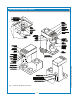
Koffee-King™ EXPLODED VIEW & PARTS LIST 2M-75804-611 Koffee-King 8900 Series Brewer CABINET & RELATED COMPONENTS 18 IL1700
Koffee-King™ EXPLODED VIEW & PARTS LIST (continued) 1 PART NO.
Koffee-King™ EXPLODED VIEW & PARTS LIST (continued) HOT WATER TANK ASSEMBLY ALT. GREY N.L.A IL1701 ITEM PART NO. 13 2C-70134 HOLD-DOWN STRAP ALL 14 2C-73457 NUT, HEX 8-32 KEPS ALL 2M-75804-611 Koffee-King 8900 Series Brewer 50 DESCRIPTION WS-8512-51 THERMOSTAT (BLACK BODY - INCL. SEAL & MOUNTING SCREWS) N.L.A THERMO (ALT) (GRAY BODY - INCL.
Koffee-King™ EXPLODED VIEW & PARTS LIST (continued) INTERNAL PLUMBING COMPONENTS IL1702 DESCRIPTION USED ON 8 2V-70104 FORMED TUBE, FAUCET OUTLET ASSEMBLY 10-7/8" LONG 8540, 8572, 8574 9 2V-70111 FORMED TUBE, FAUCET COIL INLET ASSEMBLY 8540, 8572, 8574 10 2E-70451 ADAPTER, 1/4" MALE FLARE x 1/8" FPT BRASS 8540, 8572, 8574 11 2V-70352 VALVE, FAUCET SHUT OFF, NEEDLE SEAT 8540, 8572, 8574 12 2J-75681 BRAIDED TUBE, FAUCET INLET 6MM x 299MM (11-3/4") LONG 8540, 8572, 8574 18 2K-70096 EL
Koffee-King™ EXPLODED VIEW & PARTS LIST (continued) ELECTRICAL COMPONENTS IL1703 ITEM 2 30 31 32 35 PART NO.
Koffee-King™ WIRING DIAGRAMS HI-LIMIT BLACK BLUE WHITE RED RED ELEMENT UPPER WARMER WHITE LOWER WARMER BLACK BLACK BLACK THERMOSTAT BROWN BROWN BLACK WHITE TIMER GREEN WHITE WHITE MODEL NUMBER 8540 and 8541 WHITE WHITE BLACK SOLENOID READY LIGHT BLACK BREW SWITCH BLACK 1 2 3 WARMER SWITCH 1 2 3 WARMER SWITCH MODEL 8543 ONLY HI-LIMIT THERMOSTAT GREEN ELEMENT BLACK UPPER WARMER BLUE BLACK RED RED LOWER WARMER WHITE WHITE BLACK WHITE 1 2 3 WARMER SWITCH READY LIGHT 1 2 3
Koffee-King™ WIRING DIAGRAMS (continued) HI-LIMIT RED WHITE WHITE BLUE RED WHITE BLACK BREW SWITCH THERMOSTAT 1 2 3 WARMER SWITCH 1 2 3 WARMER SWITCH 1 2 3 WARMER SWITCH LEFT WARMER RIGHT WARMER REAR WARMER BLACK WHITE BLUE WHITE RED RED BLACK WHITE ORANGE ELEMENT BLACK BROWN BLACK WHITE BROWN REaDY LIGHT HI-LIMIT TIMER WHITE WHITE LINE RED GND WHITE BLACK GREEN 2M-75804-611 Koffee-King 8900 Series Brewer WHITE BLACK SOLENOID LINE REAR WARMER WHITE WHITE MODEL
2M-75804-611 Koffee-King 8900 Series Brewer NOTES: 25
2M-75804-611 Koffee-King 8900 Series Brewer NOTES: 26
10 Sunnen Drive, St. Louis, MO 63143 telephone: 314-678-6336 fax: 314-781-2714 www.wellsbloomfield.