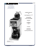
601 BLOOMFIELD INDUSTRIES 10 Sunnen Drive St. Louis, MO 63143 telephone: 314-678-6336 fax: 314-781-2714 www.wellsbloomfield.com OWNERS MANUAL for INTEGRITY™ DECANTER COFFEE BREWERS MODELS 9003 9010 9012 9016 Includes: Installation Use & Care Servicing Instructions Model 9012 Brewers with optional 8900-Series Glass Decanters p/n 2M-75815 Rev.
WARRANTY STATEMENT All electrical equipment manufactured by WELLS BLOOMFIELD, LLC is warranted against defects in materials and workmanship for a period of one year from the date of original installation or eighteen (18) months from the date of shipment from our factory, whichever comes first, and is for the benefit of the original purchaser, except that: a. airpots carry a 30 day parts warranty only. b. dispensers; i.e., tea and coffee carry a 90 days parts warranty only, excludes decanters.
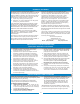
TABLE OF CONTENTS WARRANTY STATEMENT SPECIFICATIONS FEATURES & OPERATING CONTROLS PRECAUTIONS & GENERAL INFORMATION AGENCY APPROVAL INFORMATION INSTALLATION INSTRUCTIONS OPERATION BREWING COFFEE CLEANING INSTRUCTIONS TROUBLESHOOTING SUGGESTIONS SERVICING INSTRUCTIONS Deliming Instructions EXPLODED VIEWS & PARTS LISTS WIRING DIAGRAMS xi 1 2 3 3 4 6 8 9 10 11 16 18 22 Thank You for purchasing this Wells Bloomfield appliance.
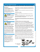
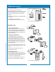
FEATURES AND OPERATING CONTROLS HOT WATER FAUCET (certain models) IL1614a Fig.
PRECAUTIONS AND GENERAL INFORMATION WARNING WARNING WARNING WARNING WARNING: ELECTRIC SHOCK HAZARD All servicing requiring access to non-insulated components must be performed by qualified service personnel. Do not open any access panels which require the use of tools. Failure to heed this warning can result in electrical shock. WARNING: INJURY HAZARD All installation procedures must be performed by qualified personnel with full knowledge of all applicable electrical and plumbing codes.
INSTALLATION INSTRUCTIONS READ THIS CAREFULLY BEFORE STARTING THE INSTALLATION CAUTION: EQUIPMENT DAMAGE DO NOT plug in or energize this appliance until all Installation Instructions are read and followed. Damage to the Brewer will occur if these instructions are not followed. CAUTION: Unstable Equipment Hazard It is very important for safety and for proper operation that the brewer is level and stable when standing in its final operating position.
INSTALLATION INSTRUCTIONS (continued) In some areas, local codes require a backflow preventer (check valve) to be installed on the inlet water line. If a backflow preventer is used, you must install a water hammer arrester in the incoming line, between the backflow preventer and the brewer inlet, as far away from the brewer as space will allow. This will relieve the excessive back pressures that can cause faucet leaks and solenoid malfunctions.
OPERATION IL1617 Fig. 4 Brewer Operation Diagram A. START-UP For initial start-up, or if the brewer has not been used for an extended period of time: • Be sure spray disk and brew gasket are properly installed in the brew head. • Be sure the water supply is properly connected and the water supply valve is turned ON. • Be sure the WATER TANK IS FILLED BEFORE plugging the brewer into a receptacle, or otherwise connecting brewer to electrical power the water tank must be filled.
OPERATION (continued) WATER HEATER Water temperature is sensed by a thermobulb inserted into the water tank. This temperature signal is fed to the thermostat, which controls line power to the heating element. The setpoint temperature is adjustable at the thermostat. The element is protected from over-temperature by a hi-limit thermostat. IL1619 Fig.
BREWING COFFEE BURN HAZARD Exposed surfaces of the brewer, brew chamber and decanter may be HOT to the touch, and can cause serious burns. CAUTION: BURN HAZARD To avoid splashing or overflowing hot liquids, ALWAYS place an empty decanter under the brew chamber before starting the brew cycle. Failure to comply can cause serious burns. CAUTION: BURN HAZARD After a brew cycle, brew chamber contents are HOT. Remove the brew chamber and dispose of used grounds with care.
CLEANING INSTRUCTIONS PROCEDURE: Clean Coffee Brewer CAUTION: PRECAUTIONS: Disconnect brewer from electric power. Allow brewer to cool. FREQUENCY: Daily TOOLS: Mild Detergent, Clean Soft Cloth or Sponge Bristle Brush. BURN HAZARD Brewing and serving temperatures of coffee are extremely hot. Hot coffee will cause serious skin burns. CAUTION: 1. Disconnect brewer from electric power. Allow brewer to cool before cleaning. SHOCK HAZARD Do not submerge or immerse brewer in water. 2.
TROUBLESHOOTING SUGGESTIONS Water won’t heat Trips hi-limit safety at start-up Coffee level low (pour-over) POSSIBLE CAUSE Check power supply cord Check / reset circuit breaker Thermostat set too low Set for desired temperature Hi-Limit thermostat tripped Allow to cool, Reset hi-limit (8786, 8788) Damaged internal component or wiring Examine wiring & connectors, thermostat and heating element, Repair/replace as needed No Water or too little water added at start-up Be sure to add sufficient water
SERVICING INSTRUCTIONS ACCESS PANELS CAUTION: Each warmer plate has a center stud which screws into a bracket. Warmer plates on Canadian brewers are secured with a nut. Remove button plug on bottom of brewer to access nut on main warmer. Remove top panel to access nuts on top warmers. Remove warmer plates by turning counter-clockwise. Solenoid door is held by two screws and a retaining lip. IN-LINE BREWERS: Top panel is held by two screws at the rear and a retaining lip at the front.
SERVICING INSTRUCTIONS (continued) TEMPERATURE ADJUSTMENT Unplug power cord or turn circuit breaker OFF. Remove top panel. CAUTION: SHOCK HAZARD These procedures involve exposed electrical circuits. These procedures are to be performed by qualified technical personnel only. Pull vent tube out of tank lid and insert a thermometer of known accuracy in vent hole. Reconnect brewer to electrical power. IL1607 IMPORTANT: A mechanical thermostat will maintain temperature within ±5ºF.
SERVICING INSTRUCTIONS (continued) TIMER ADJUSTMENT The amount of water dispensed automatically during a brew cycle is controlled by the timer. Place empty decanter under brew chamber. Press BREW button. Brewer should dispense one decanter of water. To adjust amount: Remove brew chamber and button plug. Adjust knob on timer; clockwise increases time. Run several cycles to check amount of water delivered. Replace button plug. REMOVE TANK LID ASSEMBLY Unplug brewer or turn circuit breaker OFF.
SERVICING INSTRUCTIONS (continued) IMPORTANT: When replacing heating element, also replace seal gaskets. REPLACE HEATING ELEMENT Remove tank lid assembly as described on page 13. Remove two hex nuts holding element to cover. Pull element from mounting holes. Reassemble in reverse order. REPLACE SOLENOID Symptom: Automatic brewer will not flow water; or, automatic brewer drips continuously from brew head. NOTE: Wrench p/n 86660 is designed to allow easy removal of the hoses from the plastic solenoid valve.
SERVICING INSTRUCTIONS (continued) REPLACE TIMER ASSEMBLY Unplug power cord or turn circuit breaker OFF. Remove front panel. Remove knob and three screws holding timer to bracket. Disconnect wiring to timer. Reassemble in reverse order. Adjust timer as described on page 13 REPLACE HOT WATER FAUCET COIL Symptom: Brewer drips continuously from brew head, except when faucet valve is turned OFF. Remove tank lid assembly per above. IMPORTANT: When replacing water faucet coil, also replace seal gaskets.
SERVICING INSTRUCTIONS (continued) CHEMICAL BURN HAZARD Deliming chemicals may be caustic. Wear appropriate protective gloves and goggles during this procedure. Never siphon deliming chemicals or solutions by mouth. This operation should only be performed by qualified and experienced service personnel. IMPORTANT: DO NOT spill, splash or pour water or deliming solution into or over any internal component other than the inside of the water tank.
SERVICING INSTRUCTIONS (continued) 7. Set the tank back into the brewer. Reassemble the tank lid to the water tank. Make sure the gasket is properly in place, then reinstall the hold-down strap. 8. Reinstall wiring to heating element and thermostat. Reinstall the hi-limit thermostat (if removed). For brewers with hot water faucet, reassemble faucet piping. Verify that all internal components are dry, then reinstall the top panel. 9.
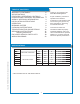
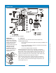
EXPLODED VIEW & PARTS LIST HOT WATER TANK ASSEMBLY IL1622 ITEM PART NO. 13 2C-70134 HOLD-DOWN STRAP 9010, 9012(CA), 9016(EX) USED ON 14 2C-73457 NUT, HEX 8-32 KEPS 9010, 9012(CA), 9016(EX) WS-8512-51 THERMOSTAT (BLACK BODY - INCL. SEAL & MOUNTING SCREWS) WS-86280 THERMO (ALT) (GRAY BODY - INCL.
EXPLODED VIEW & PARTS LIST (continued) CABINET PLUMBING COMPONENTS 601 p/n 2M-75815 9003, 9010, 9012, 9016 Decanter Coffee Brewer IL1623 ITEM PART NO.
EXPLODED VIEW & PARTS LIST (continued) ELECTRICAL COMPONENTS IL1624 2 30 31 PART NO.
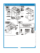
EXPLODED VIEW & PARTS LIST (continued) CABINET COMPONENTS IL1625 ITEM PART NO.
22 K AC BL GE AN LK LU E 6B 7B HT TANK CVR HARNESS PN 70455 ITE WH K AC BL OR AC K BL MAIN WIRE HARNESS PN 70448 9W 9 1 4 0 P1 LA CK 45 70 7B E LU 6B TE HI 3W E E HIT NG RA 1O CK 9W LA 7B OR CT 3 NE 2 5R ED N CO ED 5R CK LA 7B T WH CK LA 7B 3 1 3W HIT E OR CT E NN CO 2 C3 E NG RA 8O L 4B E NG RA 1O K AC E 4 3 WN K 22 3W HI TE C1 ITE WH OR CT 1 NE 2 CK N CO AC L 7B HIT 3W 52 4 70 E NG RO 2B LA 7B LOWE
601 p/n 2M-75815 9003, 9010, 9012, 9016 Decanter Coffee Brewer WIRING DIAGRAMS 9010 23
601 p/n 2M-75815 9003, 9010, 9012, 9016 Decanter Coffee Brewer WIRING DIAGRAMS 9016 24
601 p/n 2M-75815 9003, 9010, 9012, 9016 Decanter Coffee Brewer NOTES 25
10 Sunnen Drive, St. Louis, MO 63143 telephone: 314-678-6336 fax: 314-781-2714 www.wellsbloomfield.