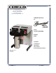
625 10 Sunnen Drive St. Louis, MO 63143 telephone: 314-678-6336 fax: 314-781-2714 www.bloomfieldworldwide.com OWNERS MANUAL for DUAL COFFEE BREWER MODEL 8792 Includes: Installation Operation Use & Care Servicing Instructions Model 8792 Brewer with optional 7759 Airpots p/n 2m-75873 Rev.
WARRANTY STATEMENT All electrical equipment manufactured by BLOOMFIELD is warranted against defects in materials and workmanship for a period of (1 year labor, two year parts) from the date of original installation and is for the benefit of the original purchaser, except that: a. airpots carry a 30 day parts warranty only. b. dispensers; i.e., tea and coffee carry a 90 days parts warranty only, excludes decanters. c.
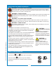
TABLE OF CONTENTS WARRANTY STATEMENT SPECIFICATIONS FEATURES & OPERATING CONTROLS PRECAUTIONS & GENERAL INFORMATION AGENCY LISTING INFORMATION INSTALLATION INSTRUCTIONS OPERATION BREWING COFFEE CLEANING INSTRUCTIONS TROUBLESHOOTING SUGGESTIONS SERVICING INSTRUCTIONS Deliming Instructions EXPLODED VIEWS & PARTS LISTS WIRING DIAGRAMS xi 1 2 3 3 4 6 8 9 10 11 16 18 22 Thank You for purchasing this Bloomfield appliance.
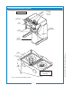
FEATURES AND OPERATING CONTROLS POUR-OVER COVER AIRPOT BREWER POUR-OVER OPENING "READY TO BREW" LIGHT BREW SWITCH ON-OFF SWITCHES BREW CHAMBER HOT WATER FAUCET BREW NOZZLE SPRAY HEAD GASKET SPRAY DISK TIMER ACCESS BREW HEADS (BREW CHAMBERS REMOVED) IL1712A Fig.
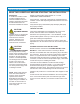
PRECAUTIONS AND GENERAL INFORMATION WARNING: ELECTRIC SHOCK HAZARD WARNING WARNING WARNING All servicing requiring access to non-insulated components must be performed by qualified service personnel. Do not open any access panels which require the use of tools. Failure to heed this warning can result in electrical shock. WARNING: INJURY HAZARD All installation procedures must be performed by qualified personnel with full knowledge of all applicable electrical and plumbing codes.
INSTALLATION INSTRUCTIONS READ THIS CAREFULLY BEFORE STARTING THE INSTALLATION REFER TO EXPLODED VIEWS Pages 18 - 21 for COMPONENT NAMES/NUMBERS Unpack the unit. Inspect all components for completeness and condition. Ensure that all packing materials have been removed from the unit. Verify that the Spray Head Gasket (#33) and Spray Disk (#34) are properly installed.
INSTALLATION INSTRUCTIONS (continued) NSF requires that the brewer be able to be moved for cleaning underneath. A flex line or loops of copper tubing will satisfy this requirement. See Figure 2 below. SOLENOID STRAINER WASHER COPPER LOOPS OR FLEX LINES (PROVIDED BY PLUMBER) INLET FITTINGS WARNING SHUT-OFF VALVE (PROVIDED BY PLUMBER) WATER SUPPLY FLOW NOTE DUAL 1/4” FEMALE FLARE FITTINGS (PROVIDED BY PLUMBER) IL1716 Fig.
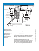
OPERATION TANK VENT TUBE BASIN HOT WATER FAUCET (RIGHT SIDE ONLY) FAUCET SHUT-OFF (RIGHT SIDE ONLY) WATER TANK TIMER BREW HEAD FAUCET WATER HEATING COIL (RIGHT SIDE ONLY) BRAIDED HOSE FAUCET SUPPLY (RIGHT SIDE ONLY) BREW CHAMBER SOLENOID W/ FAUCET BYPASS (RIGHT SIDE) SOLENOID (SINGLE - LEFT SIDE) INLET FITTING IL1718 Fig. 4 Brewer Operation Diagram A.
OPERATION (continued) WATER HEATER HI-LIMIT THERMOSTAT Water temperature is sensed by a thermobulb inserted into the water tank. This temperature signal is fed to the thermostat, which controls line power to the heating element. THERMOBULB The setpoint temperature is adjustable at the thermostat. HEATER ELEMENT THERMOSTAT The element is protected from overtemperature by a hi-limit thermostat. Fig.
BREWING COFFEE BURN HAZARD Exposed surfaces of the brewer, brew chamber and airpot or server may be HOT to the touch, and can cause serious burns. CAUTION: BURN HAZARD To avoid splashing or overflowing hot liquids, ALWAYS place an empty airpot or server under the brew chamber before starting the brew cycle. Failure to comply can cause serious burns. CAUTION: BURN HAZARD After a brew cycle, brew chamber contents are HOT. Remove the brew chamber and dispose of used grounds with care.
CLEANING INSTRUCTIONS PROCEDURE: Clean Coffee Brewer CAUTION: PRECAUTIONS: Disconnect brewer from electric power. Allow brewer to cool. FREQUENCY: Daily TOOLS: Mild Detergent, Clean Soft Cloth or Sponge Bristle Brush, Bottle Brush BURN HAZARD Brewing and serving temperatures of coffee are extremely hot. Hot coffee will cause serious skin burns. CAUTION: 1. Disconnect brewer from electric power. SHOCK HAZARD Allow brewer to cool before cleaning. Do not submerge or immerse brewer in water. 2.
TROUBLESHOOTING SUGGESTIONS Water won’t heat Coffee level low (pour-over) Coffee level too high or low (automatic) Brew chamber overflows Sprays water from brew head No brew (automatic) No flow from hot water faucet Poor coffee quality POSSIBLE CAUSE SUGGESTED REMEDY Brewer unplugged or circuit breaker tripped Check power supply cord Thermostat set too low Set for desired temperature Hi-Limit thermostat tripped Check / reset circuit breaker Allow to cool Reset hi-limit (8786, 8788) Damaged in
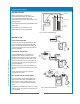
SERVICING INSTRUCTIONS ACCESS PANELS CAUTION TOP PANEL: Remove top panel to access hot water tank, thermostat, heating elements, brew circuit tubing, faucet valve and piping. Top panel is held by two screws at the rear and a retaining lip at the front. FRONT PANEL: Remove front panel to access timer, terminal block and solenoid. Front panel is held by two screws at the bottom and a retaining lip at the top.
SERVICING INSTRUCTIONS (continued) TEMPERATURE ADJUSTMENT CAUTION: SHOCK HAZARD Unplug power cord or turn circuit breaker OFF. Remove top panel. These procedures involve exposed electrical circuits. These procedures are to be performed by qualified technical personnel only. Pull vent tube out of tank lid and insert a thermometer of known accuracy in vent hole. Reconnect brewer to electrical power.
SERVICING INSTRUCTIONS (continued) TIMER ADJUSTMENT The amount of water dispensed automatically during a brew cycle is controlled by the timer. Place empty decanter under brew chamber. Press BREW button. Brewer should dispense one decanter of water. To adjust amount: Remove brew chamber and button plug. Adjust knob on timer; clockwise increases time. Run several cycles to check amount of water delivered. Replace button plug. REMOVE TANK LID ASSEMBLY Unplug brewer or turn circuit breaker OFF.
SERVICING INSTRUCTIONS (continued) IMPORTANT: When replacing heating element, also replace seal gaskets. REPLACE HEATING ELEMENT Remove tank lid assembly as described on page 13. Remove two hex nuts holding element to cover. Pull element from mounting holes. Reassemble in reverse order. WHITE CLINCH RING METAL FITTING #86660 WRENCH WRENCH METAL FITTING CLINCH RING SLIDE WRENCH BETWEEN VALVE AND HOSE FITTING PRESS CLINCH RING TOWARD METAL FITTING TO RELEASE IL1699 Fig.
SERVICING INSTRUCTIONS (continued) REPLACE TIMER ASSEMBLY Unplug power cord or turn circuit breaker OFF. Remove front panel. Remove knob and three screws holding timer to bracket. Disconnect wiring to timer. Reassemble in reverse order. Adjust timer as described on page 13 REPLACE HOT WATER FAUCET COIL Symptom: Brewer drips continuously from brew head, except when faucet valve is turned OFF. IMPORTANT: When replacing water faucet coil, also replace seal gaskets. Remove tank lid assembly per above.
SERVICING INSTRUCTIONS (continued) CHEMICAL BURN HAZARD Deliming chemicals may be caustic. Wear appropriate protective gloves and goggles during this procedure. Never siphon deliming chemicals or solutions by mouth. This operation should only be performed by qualified and experienced service personnel. IMPORTANT: DO NOT spill, splash or pour water or deliming solution into or over any internal component other than the inside of the water tank.
EXPLODED VIEW & PARTS LIST HOT WATER TANK ASSEMBLY 14 60 59 61 68 50 55 62 62 13 52 54 66a 56 57 66b 56 66 58 50 67 ALTERNATE IL1715 ITEM PART NO. 13 2C-70134 HOLD-DOWN STRAP BOTH SIDES 14 2C-73457 NUT, HEX 8-32 KEPS BOTH SIDES 625 p/n 2M-75873 8792, 8793 Dual Coffee Brewer 50 DESCRIPTION WS-8512-51 THERMOSTAT (BLACK BODY - INCL. SEAL & MOUNTING SCREWS) WS-86280 THERMO (ALT) (GRAY BODY - INCL.
EXPLODED VIEW & PARTS LIST (continued) CABINET PLUMBING COMPONENTS IL1720 PART NO.
EXPLODED VIEW & PARTS LIST (continued) ELECTRICAL COMPONENTS 34 35 45 36t 625 p/n 2M-75873 8792, 8793 Dual Coffee Brewer IL1721A ITEM PART NO. 31 2E-70733 DESCRIPTION USED ON SWITCH, MOMENTARY ROCKER, BREW BOTH 32 2J-72671 INDICATOR, 120V, READY-TO-BREW BOTH 34 2E-72936 SWITCH ROCKER ON-OFF BOTH 35 2P-70128 TIMER, 2-MINUTE (WITH DIAL & KNOB) 120V BOTH 36t 2E-70709 TERMINAL BLOCK, 4P LEFT SIDE ONLY 2E-75753 SOLENOID W/BYPASS, 120V, .
EXPLODED VIEW & PARTS LIST (continued) CABINET COMPONENTS PART NO.
625 p/n 2M-75873 8792, 8793 Dual Coffee Brewer WIRING DIAGRAM p/n 74810 22
10 Sunnen Drive, St. Louis, MO 63143 telephone: 314-678-6336 fax: 314-781-2714 www.bloomfieldworldwide.