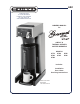
622 10 Sunnen Drive St. Louis, MO 63143 telephone: 314-678-6336 fax: 314-781-2714 www.wellsbloomfield.com OWNERS MANUAL for AIRPOT & THERMAL SERVER COFFEE BREWERS MODELS 8778 8780 8782 8783 8785 8786 8788 Includes: Installation Use & Care Servicing Instructions Model 8780 Brewer with optional 7750 Thermal Server p/n 2M-75854 Rev.
WARRANTY STATEMENT All electrical equipment manufactured by BLOOMFIELD is warranted against defects in materials and workmanship for a period of (1 year labor, two year parts) from the date of original installation and is for the benefit of the original purchaser, except that: a. airpots carry a 30 day parts warranty only. b. dispensers; i.e., tea and coffee carry a 90 days parts warranty only, excludes decanters. c.
TABLE OF CONTENTS WARRANTY STATEMENT SPECIFICATIONS FEATURES & OPERATING CONTROLS PRECAUTIONS & GENERAL INFORMATION AGENCY LISTING INFORMATION INSTALLATION INSTRUCTIONS OPERATION BREWING COFFEE CLEANING INSTRUCTIONS TROUBLESHOOTING SUGGESTIONS SERVICING INSTRUCTIONS Deliming Instructions EXPLODED VIEWS & PARTS LISTS WIRING DIAGRAMS xi 1 2 3 3 4 6 8 9 10 11 16 18 22 Thank You for purchasing this Bloomfield appliance.
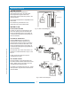
FEATURES AND OPERATING CONTROLS POUR-OVER COVER POUR-OVER OPENING “READY TO BREW” LIGHT BREW SWITCH HOT WATER FAUCET AIROT (BREWING POSITION) IL1705 Fig.
PRECAUTIONS AND GENERAL INFORMATION WARNING: ELECTRIC SHOCK HAZARD WARNING All servicing requiring access to non-insulated components must be performed by qualified service personnel. Do not open any access panels which require the use of tools. Failure to heed this warning can result in electrical shock. WARNING: INJURY HAZARD WARNING All installation procedures must be performed by qualified personnel with full knowledge of all applicable electrical and plumbing codes.
INSTALLATION INSTRUCTIONS READ THIS CAREFULLY BEFORE STARTING THE INSTALLATION CAUTION: EQUIPMENT DAMAGE DO NOT plug in or energize this appliance until all Installation Instructions are read and followed. Damage to the Brewer will occur if these instructions are not followed. CAUTION: UNSTABLE EQUIPMENT HAZARD It is very important for safety and for proper operation that the brewer is level and stable when standing in its final operating position.
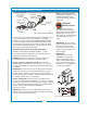
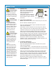
INSTALLATION INSTRUCTIONS (continued) COPPER LOOPS OR FLEX LINES (PROVIDED BY PLUMBER) SHUT-OFF VALVE (PROVIDED BY PLUMBER) WATER SUPPLY NOTE: This equipment must be installed in compliance with all applicable federal, state and local plumbing codes and ordinances. SOLENOID STRAINER WASHER WATER INLET FITTING FLOW IL1615 Fig. 2 Water Supply Installation In some areas, local codes require a backflow preventer (check valve) to be installed on the inlet water line.
OPERATION IL1706 IMPORTANT: Tank must be full of water before connecting brewer to electrical power. Heating elements will be damaged if allowed to operate without being fully submerged in water. Damage caused by operating the brewer without water in the tank is NOT COVERED BY WARRANTY. A. START-UP For initial start-up, or if the brewer has not been used for an extended period of time: Be sure spray disk and brew gasket are properly installed in the brew head.
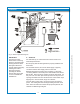
OPERATION (continued) WATER HEATER HI-LIMIT THERMOSTAT Water temperature is sensed by a thermobulb inserted into the water tank. This temperature signal is fed to the thermostat, which controls line power to the heating element. THERMOBULB The setpoint temperature is adjustable at the thermostat. The element is protected from overtemperature by a hi-limit thermostat.
BREWING COFFEE BURN HAZARD Exposed surfaces of the brewer, brew chamber and airpot or server may be HOT to the touch, and can cause serious burns. A. PREPARATION Place one (1) genuine Bloomfield paper filter in the brew chamber. Add a pre-measured amount of fresh coffee grounds. Gently shake the brew chamber to level the bed of grounds. Slide the brew chamber into place under the brew head.
CLEANING INSTRUCTIONS PROCEDURE: Clean Coffee Brewer CAUTION: PRECAUTIONS: Disconnect brewer from electric power. Allow brewer to cool. FREQUENCY: Daily TOOLS: Mild Detergent, Clean Soft Cloth or Sponge Bristle Brush, Bottle Brush BURN HAZARD Brewing and serving temperatures of coffee are extremely hot. Hot coffee will cause serious skin burns. CAUTION: SHOCK HAZARD Do not submerge or immerse brewer in water. 1. Disconnect brewer from electric power. Allow brewer to cool before cleaning. 2.
TROUBLESHOOTING SUGGESTIONS Water won’t heat Coffee level low (pour-over) Coffee level too high or low (automatic) Brew chamber overflows Sprays water from brew head No brew (automatic) No flow from hot water faucet Poor coffee quality POSSIBLE CAUSE SUGGESTED REMEDY Brewer unplugged or circuit breaker tripped Check power supply cord Thermostat set too low Set for desired temperature Hi-Limit thermostat tripped Allow to cool, Reset hi-limit (8786, 8788) Damaged internal component or wiring E
SERVICING INSTRUCTIONS ACCESS PANELS CAUTION: TOP PANEL: Remove top panel to access hot water tank, thermostat, heating elements, brew circuit tubing, faucet valve and piping. SHOCK HAZARD Top panel is held by two screws at the rear and a retaining lip at the front. FRONT PANEL: Remove front panel to access timer, terminal block and solenoid. Front panel is held by two screws at the bottom and a retaining lip at the top.
SERVICING INSTRUCTIONS (continued) TEMPERATURE ADJUSTMENT CAUTION: SHOCK HAZARD These procedures involve exposed electrical circuits. These procedures are to be performed by qualified technical personnel only. Unplug power cord or turn circuit breaker OFF. Remove top panel. Pull vent tube out of tank lid and insert a thermometer of known accuracy in vent hole. Reconnect brewer to electrical power. IL1607 IMPORTANT: A mechanical thermostat will maintain temperature within ±5ºF.
SERVICING INSTRUCTIONS (continued) TIMER ADJUSTMENT The amount of water dispensed automatically during a brew cycle is controlled by the timer. Place empty decanter under brew chamber. Press BREW button. Brewer should dispense one decanter of water. To adjust amount: Remove brew chamber and button plug. Adjust knob on timer; clockwise increases time. Run several cycles to check amount of water delivered. Replace button plug. REMOVE TANK LID ASSEMBLY Unplug brewer or turn circuit breaker OFF.
SERVICING INSTRUCTIONS (continued) IMPORTANT: When replacing heating element, also replace seal gaskets. REPLACE HEATING ELEMENT Remove tank lid assembly as described on page 13. Remove two hex nuts holding element to cover. Pull element from mounting holes. Reassemble in reverse order. REPLACE SOLENOID Symptom: Automatic brewer will not flow water; or, automatic brewer drips continuously from brew head. NOTE: Wrench p/n 86660 is designed to allow easy removal of the hoses from the plastic solenoid valve.
SERVICING INSTRUCTIONS (continued) REPLACE TIMER ASSEMBLY Unplug power cord or turn circuit breaker OFF. Remove front panel. Remove knob and three screws holding timer to bracket. Disconnect wiring to timer. Reassemble in reverse order. Adjust timer as described on page 13 REPLACE HOT WATER FAUCET COIL Symptom: Brewer drips continuously from brew head, except when faucet valve is turned OFF. IMPORTANT: When replacing water faucet coil, also replace seal gaskets. Remove tank lid assembly per above.
SERVICING INSTRUCTIONS (continued) CHEMICAL BURN HAZARD Deliming chemicals may be caustic. Wear appropriate protective gloves and goggles during this procedure. Never siphon deliming chemicals or solutions by mouth. This operation should only be performed by qualified and experienced service personnel. IMPORTANT: DO NOT spill, splash or pour water or deliming solution into or over any internal component other than the inside of the water tank.
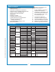
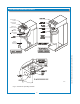
EXPLODED VIEW & PARTS LIST ASSEMBLY, HOT WATER TANK 622 2M-75854 Owners Manual Gourmet 1000 Airpot/Thermal IL1708 ITEM PART NO. 13 2C-70134 14 2C-73457 50 WS-8512-51 52 54 55 DESCRIPTION HOLD-DOWN STRAP USED ON ALL NUT, HEX 8-32 KEPS ALL THERMOSTAT (BLACK BODY - INCL.
EXPLODED VIEW & PARTS LIST (continued) CABINET PLUMBING COMPONENTS IL1709 PART NO.
EXPLODED VIEW & PARTS LIST (continued) ELECTRICAL COMPONENTS IL1710 ITEM PART NO.
EXPLODED VIEW & PARTS LIST (continued) CABINET COMPONENTS 622 2M-75854 Owners Manual Gourmet 1000 Airpot/Thermal IL1711 21
EXPLODED VIEW & PARTS LIST (continued) CABINET COMPONENTS ITEM PART NO. 21 2A-43201 Spacer, .171 ID x .
WIRING DIAGRAM 120VAC, POUR-OVER 1800 WATT MODELS” 8778 8783 8785 1500 WATT (Canadian) MODELS: 8778CA 8783CA 8785CA 120VAC, AUTOMATIC 622 2M-75854 Owners Manual Gourmet 1000 Airpot/Thermal 1800 WATT MODELS” 8780 8782 8782XL 1500 WATT (Canadian) MODELS: 8780CA 8782CA 8782XLCA (BROWN 230V) BLACK 14 GA WHITE 14 GA (BLUE 230V) 22
622 2M-75854 Owners Manual Gourmet 1000 Airpot/Thermal WIRING DIAGRAM (continued) 23
622 2M-75854 Owners Manual Gourmet 1000 Airpot/Thermal NOTES
622 2M-75854 Owners Manual Gourmet 1000 Airpot/Thermal NOTES
10 Sunnen Drive, St. Louis, MO 63143 telephone: 314-678-6336 fax: 314-781-2714 www.wellsbloomfield.