641 10 Sunnen Drive St. Louis, MO 63143 telephone: 314-678-6336 fax: 314-781-2714 www.bloomfieldworldwide.com OWNERS MANUAL for E. B. C.™ Electronic Brew Control ™ DECANTER COFFEE BREWERS Models 1012 Brewer with optional 8900-Series Glass Decanters MODELS 1012 1040 1072 Includes: Installation Use & Care Servicing Instructions Model 1072 Brewer with optional 8900-Series Glass Decanters E.B.C.™ brewers are protected under U. S. Patent # 5,704,275 Other U. S. and Canadian patents pending.
WARRANTY STATEMENT All equipment manufactured by Bloomfield is warranted against defects in materials and workmanship for the time periods listed in the chart starting from the date the equipment is placed into service and is for the benefit of the original purchaser: THE FOREGOING OBLIGATION IS EXPRESSLY GIVEN IN LIEU OF ANY OTHER WARRANTIES, EXPRESSED OR IMPLIED, INCLUDING ANY IMPLIED WARRANTY OF MERCHANTABILITY OR FITNESS FOR A PARTICULAR PURPOSE, WHICH ARE HEREBY EXCLUDED.
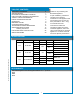
TABLE OF CONTENTS WARRANTY STATEMENT xi SPECIFICATIONS 1 FEATURES & OPERATING CONTROLS 2 PRECAUTIONS & GENERAL INFORMATION 3 AGENCY LISTING INFORMATION 3 INSTALLATION INSTRUCTIONS 4 OPERATION 6 BREWING COFFEE 10 CLEANING INSTRUCTIONS 11 TROUBLESHOOTING SUGGESTIONS 12 SERVICING INSTRUCTIONS 14 Deliming Instructions 20 EXPLODED VIEWS & PARTS LISTS 22 WIRING DIAGRAMS 29 Thank You for purchasing this Bloomfield appliance.
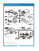
641 75844 Owners Manual E.B.C. Decanter 641 p/n 2M-75844 1012 1040 1072 Owmers Manual FEATURES AND AND OPERATING OPERATING CONTROLS FEATURES Fig. 11 Features Features && Operating Operating Controls Controls Fig.
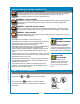
PRECAUTIONS AND GENERAL INFORMATION WARNING: ELECTRIC SHOCK HAZARD All servicing requiring access to non-insulated components must be performed by qualified service personnel. Do not open any access panels which require the use of tools. Failure to heed this warning can result in electrical shock. WARNING: INJURY HAZARD All installation procedures must be performed by qualified personnel with full knowledge of all applicable electrical and plumbing codes.
INSTALLATION INSTRUCTIONS READ THIS CAREFULLY BEFORE STARTING THE INSTALLATION CAUTION: EQUIPMENT DAMAGE DO NOT plug in or energize this appliance until all Installation Instructions are read and followed. Damage to the Brewer will occur if these instructions are not followed. CAUTION: UNSTABLE EQUIPMENT HAZARD It is very important for safety and for proper operation that the brewer is level and stable when standing in its final operating position.
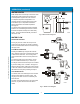
INSTALLATION INSTRUCTIONS (continued) NSF requires that the brewer be able to be moved for cleaning underneath. A flex line or loops of copper tubing will satisfy this requirement. See Figure 2 below. NOTE: This equipment must be installed to comply with all applicable federal, state and local plumbing codes and ordinances. WARNING: SHOCK HAZARD IL1615 Fig. 2 Water Supply Installation In some areas, local codes require a backflow preventer (check valve) to be installed on the inlet water line.
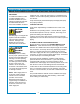
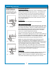
OPERATION IL2203 IMPORTANT: Tank must be full of water before connecting brewer to electrical power. Heating elements will be damaged if allowed to operate without being fully submerged in water. Damage caused by operating the brewer without water in the tank is NOT COVERED BY WARRANTY. A. START-UP For initial start-up, or if the brewer has not been used for an extended period of time: • Be sure spray disk and brew gasket are properly installed in the brew head.
OPERATION (continued) OPERATION (continued) WATER HEATER Water temperature is sensed by an electronic water temperature probe inserted into the water tank. This temperature signal is fed to the controller. The setpoint temperature is adjustable. The controller sends a command signal to the power board based upon a comparison between the setpoint temperature and actual temperature. See page 17. The power board energizes the heating elements based on the command signal from the controller.
OPERATION (continued) IMPORTANT: DO NOT energize this brewer until the water tank has been filled. Dry firing will damage heating elements. See page 6. ELECTRONIC FEATURES Energizing the Brewer When electric power is applied to the unit, the unit will beep four times and the “HEAT” & “POWER” lights will come on. The unit will be on. If the water temperature is more than 10ºF below the setpoint, the HEAT indicator will glow until water temperature reaches setpoint.
OPERATION (continued) Quality Timer Coffee looses its freshness as it sits on a warmer. The Quality Timer flashes the warmer lights 30 minutes after the last brew to remind you that the coffee is nearing the end of its useful life. After Hours™ Operation During normal operation, the controller will maintain the precise brewing temperature.
BREWING COFFEE BURN HAZARD Exposed surfaces of the brewer, brew chamber and decanter may be HOT to the touch, and can cause serious burns. CAUTION: BURN HAZARD To avoid splashing or overflowing hot liquids, ALWAYS place an empty decanter under the brew chamber before starting the brew cycle. Failure to comply can cause serious burns. CAUTION: BURN HAZARD After a brew cycle, brew chamber contents are HOT. Remove the brew chamber and dispose of used grounds with care.
CLEANING INSTRUCTIONS PROCEDURE: Clean Coffee Brewer CAUTION: PRECAUTIONS: Disconnect brewer from electric power. Allow brewer to cool. FREQUENCY: Daily TOOLS: Mild Detergent, Clean Soft Cloth or Sponge Bristle Brush. BURN HAZARD Brewing and serving temperatures of coffee are extremely hot. Hot coffee will cause serious skin burns. CAUTION: 1. Disconnect brewer from electric power. SHOCK HAZARD Allow brewer to cool before cleaning. Do not submerge or immerse brewer in water. 2.
TROUBLESHOOTING SUGGESTIONS POSSIBLE CAUSE SUGGESTED REMEDY Brewer unplugged or circuit breaker tripped Check power supply cord, Check / reset circuit breaker Temperature adjusted too low or set to off Turn on and set for desired temperature. See page 15 Hi-Limit thermostat tripped Allow to cool Damaged internal component or wiring Examine wiring & connectors, controller, power board and heating element, Repair/replace as needed Timer out of adjustment Adjust controller.
ERROR DETECTION This brewer is designed to perform a continuous internal diagnosis, and to signal faults by flashing all the lights. In fault mode, warmers, heating element and water fill solenoid are turned “off”, and most keypad functions are disabled. Error detection (all lights flashing) will occur under two conditions: •• Anytime a temperature in excess of 214ºF is detected. •• Temperature does not change by at least 2ºF within 4 minutes of tank heater being energized (HEAT light on).
SERVICING INSTRUCTIONS CAUTION: SHOCK HAZARD Opening access panels or removing warmer plates on this brew may expose uninsulated electrical components. Disconnect brewer from electrical power before removing any panel or warmer plate. ACCESS PANELS TOP PANEL: Remove top panel to access hot water tank, thermo probe, heating elements, brew circuit tubing, faucet valve and piping. Top panel is held by two screws at the rear and a retaining lip at the front.
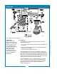
SERVICING INSTRUCTIONS (continued) TEMPERATURE ADJUSTMENT Unplug power cord or turn circuit breaker OFF. Remove top panel. Remove button plug from front panel. Pull vent tube out of tank lid and insert a thermometer of known accuracy in vent hole. Reconnect brewer to electrical power. Place empty container under brew chamber. Energize brewer CAUTION: SHOCK HAZARD These procedures involve exposed electrical circuits. These procedures are to be performed by qualified technical personnel only. IL2209 Fig.
SERVICING INSTRUCTIONS (continued) IMPORTANT: Water pressure must be between 20 p.s.i and 90 p.s.i. flowing pressure. If water pressure exceeds this value, or if water pressure varies greatly, a pressure regulator must be installed in the water supply line. BREW TIME 40 50 10 205 2 3 200 OFF 195 185 190 WATER TEMP (°F) 4 8 7 6 Remove brew chamber and button plug. On the controller, adjust SOLENOID TIME dial (BREW TIME); clockwise increases time.
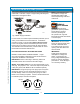
SERVICING INSTRUCTIONS (continued) REPLACE SOLENOID Unplug power cord. Turn OFF and disconnect water supply from brewer inlet fitting. Remove front panel. Remove two screws holding access door in place. Remove access door and solenoid. Unscrew inlet fitting cap to release solenoid from door. SOLENOID SCREEN WASHER INLET FITTING Remove wiring from solenoid. Large end of wrench 86660 can be used to hold solenoid inlet fitting while disconnecting supply line. REPLACE FAUCET SUPPLY HOSE Unplug power cord.
SERVICING INSTRUCTIONS (continued) IMPORTANT: When replacing water faucet coil, also replace seal gaskets. REPLACE HOT WATER FAUCET COIL (Symptom: Brewer drips continuously from brew head, except when faucet valve is turned OFF.) Remove tank lid assembly per above. Remove two hex nuts hot water coil to cover. Pull coil from mounting holes. Reassemble in reverse order. Work the seat cup out of the bonnet and off of the end of the stem.
SERVICING INSTRUCTIONS (continued) SET CONTROLLER JUMPERS Placing the jumper across Q1 sets Quality Time at 20 Minutes. Placing the jumper across Q2 sets Quality Time at 30 Minutes. Removing jumpers from both Q1 or Q2 disables Quality Timer. Placing the jumper across V1 sets Valve Time Range to 60 - 180 seconds. Removing jumper from V1 sets Valve Time Range to 10 - 80 seconds. IL2621 Fig. 19 Controller Jumpers REPLACE KEYPAD Unplug power cord or turn circuit breaker OFF. Shut off water supply valve.
SERVICING INSTRUCTIONS (continued) CHEMICAL BURN HAZARD Deliming chemicals are caustic. Wear appropriate protective gloves and goggles during this procedure. Never siphon deliming chemicals or solutions by mouth. This operation should only be performed by qualified and experienced service personnel. IMPORTANT: DO NOT spill, splash or pour water or deliming solution into or over any internal component other than the inside of the water tank.
641 p/n 2M-75844 1012 1040 1072 Owmers Manual
EXPLODED VIEW & PARTS LIST CABINET COMPONENTS - IN-LINE BREWERS 641 p/n 2M-75844 1012 1040 1072 Owmers Manual CABINET COMPONENTS - IN-LINE BREWERS 22
EXPLODED VIEW & PARTS LIST (continued) Cabinet Components for Models: 1012, 1040 ITEM 1 PART NO.
EXPLODED VIEW & PARTS LIST (continued) 641 p/n 2M-75844 1012 1040 1072 Owmers Manual CABINET COMPONENTS - LO-PROFILE BREWERS 24
EXPLODED VIEW & PARTS LIST (continued) Cabinet Components for Models: 1072 ITEM PART NO.
EXPLODED VIEW & PARTS LIST (continued) HOT WATER TANK ASSEMBLY IL2212 ITEM PART NO.
EXPLODED VIEW & PARTS LIST (continued) ELECTRICALCOMPONENTS COMPONENTS ELECTRICAL ITEM 31 35 PART NO.
EXPLODED VIEW & PARTS LIST (continued) INTERNAL PLUMBING COMPONENTS IL2214 ITEM 8 9 11 12 PART NO.
641 p/n 2M-75844 1012 1040 1072 Owmers Manual WIRING DIAGRAM 29
641 p/n 2M-75844 1012 1040 1072 Owmers Manual WIRING DIAGRAM p/n 75373 30
641 p/n 2M-75844 1012 1040 1072 Owmers Manual WIRING DIAGRAM (continued) HEATING ELEMENT 120V: 1500W 120C: 1200W 120V 120C 1 1800 1500 p/n 2M-75361 31
WIRING DIAGRAM LINE NEUTRAL J7 J3 KEYPAD J8 HEATER A VALVE B J4 J6 VALVE A HEATER B J5 J9 WP1 J10 WP2 P1 C1-3 J11 CONTROL BOARD J2 J1 HI LIMIT P2 TEMPERATURE PROBE WP3 C1-1 J12 POWER BOARD C1-2 WARMER ELEMENT 3 INLET VALVE WARMER ELEMENT 2 WARMER ELEMENT 1 TANK ELEMENT LINE 2M-Z16607 POWER SWITCH WARMING ELEMENTS ONLY ON MODELS 1012, 1040, AND 1072 POWER SWITCH ONLY ON MODELS 1086 AND 1088 230V MODELS: 1012, 1040, 1072, 1080, 1082, 1086, 1088 641 p/n 2M-75844 1012 1040 1072 Owme
641 p/n 2M-75844 1012 1040 1072 Owmers Manual NOTES
10 Sunnen Drive, St. Louis, MO 63143 telephone: 314-678-6336 fax: 314-781-2714 www.bloomfieldworldwide.