
User Manual

INSTALLATION INSTRUCTIONS (continued)
NOTE: This equipment must
be installed to comply with
all applicable federal, state
and local plumbing codes and
ordinances.
WARNING:
SHOCK HAZARD
Brewer must be properly
grounded to prevent possible
shock hazard. DO NOT
assume a plumbing line
will provide such a ground.
Electrical shock will cause death
or serious injury.
IMPORTANT: Do not connect
brewer to electrical power until
the tank is lled with water.
Pour water into the pour-over
opening until water ows from
the brew head.
IMPORTANT:
Supply power must match
nameplate for voltage and
phase. Connecting to the
wrong voltage will damage the
brewer or result in decreased
performance. Such damage is
not covered by warranty.
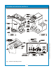
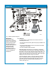
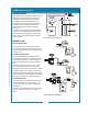
NSF requires that the brewer be able to be moved for cleaning
underneath. A ex line or loops of copper tubing will satisfy this
requirement. See Figure 2 below.
In some areas, local codes require a backow preventer (check
valve) to be installed on the inlet water line. If a backow
preventer is used, you must install a water hammer arrester
in the incoming line, between the backow preventer and the
brewer inlet, as far away from the brewer as space will allow.
This will relieve the excessive back pressures that can cause
faucet leaks and solenoid malfunctions.
ELECTRICIAN’S INSTALLATION INSTRUCTIONS
REFER TO ELECTRICAL SPECIFICATIONS - Page 1
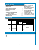
Check the nameplate to determine correct electrical service
required for the Brewer to be installed.
IMPORTANT: Before connecting to electricity, make sure
automatic brewers are connected to the water supply.
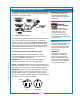
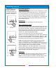
Models 1012, 1040 & 1072 (US only) are equipped with a cord
and plug. They require a 115 - 125 volt 15 amp circuit (50/60 Hz,
2 wire plus ground, with NEMA 5-15R or 5-20R Receptacle).
IMPORTANT: The ground prong of the plug is part of a system
designed to protect you from electrical shock in the event of
internal damage. Never cut off the ground prong nor twist a
blade to t an existing receptacle. Contact a licensed electrician
to install the proper circuit and receptacle.
5
IL1615
Fig. 2 Water Supply Installation
641 p/n 2M-75844 1012 1040 1072 Owmers Manual
NEMA 5-15P
PLUG
GROUND
PIN
NEMA 5-15R
RECEPTACLE
IL1686