KTT-E Series E-SB Series ELECTRIC TABLE TOPBASE TILTING KETTLE ELECTRIC BOILER STEAMER INSTALLATION MAINTENANCE INSTALLATION–- OPERATION OPERATION – - MAINTENANCE BLODGETT OVEN COMPANY BLODGETT OVEN COMPANY www.blodgett.com www.blodgett.
THIS MANUAL MUST BE RETAINED FOR FUTURE REFERENCE. READ, UNDERSTAND AND FOLLOW THE INSTRUCTIONS AND WARNINGS CONTAINED IN THIS MANUAL. FOR YOUR SAFETY Do not store or use gasoline or other flammable vapors and liquids in the vicinity of this or any other appliance. WARNING Improper installation, adjustment, alteration, service or maintenance can cause property damage, injury or death. Read the installation, operating and maintenance instructions thoroughly before installing or servicing this equipment.
IMPORTANT - READ FIRST - IMPORTANT WARNING: THE UNIT MUST BE INSTALLED BY PERSONNEL QUALIFIED TO WORK WITH ELECTRICITY AND PLUMBING. IMPROPER INSTALLATION CAN CAUSE INJURY TO PERSONNEL AND/OR DAMAGE TO THE EQUIPMENT. INSTALLATION MUST COMPLY WITH APPLICABLE CODES. NOTICE: Do not install the unit in any way which will bloc k the right side vents , or within 12 inches of a heat source such as a braising pan , deep fryer , char broiler or convection oven.
IMPORTANT - READ FIRST - IMPORTANT WARNING: DO NOT EXPOSE SKIN TO ESCAPING STEAM. SEVERE BURNS CAN RESULT. CAUTION: MAKING ANY ELECTRICAL OR MECHANICAL CHANGE IN THE UNIT WITHOUT PRIOR WRITTEN APPROVAL FROM ENGINEERING WILL VOID ALL WARRANTIES. WARNING: ALL POTENTIAL USERS OF THE EQUIPMENT SHOULD BE TRAINED IN SAFE AND CORRECT OPERATING PROCEDURES. WARNING: DO NOT OPERATE THE UNIT UNLESS ALL REMOVABLE PANELS (RIGHT, LEFT, FRONT AND REAR) HAVE BEEN PROPERLY INSTALLED.
Table of Contents Important Operator Warnings ..................................................... page 1-2 References..................................................................................... page 3 Equipment Description.................................................................. page 4 Water Quality and Treatment ......................................................... page 5 Installation ..................................................................................
Equipment Description WARNING THE UNIT MUST BE INSTALLED BY PERSONNEL WHO ARE QUALIFIED TO WORK WITH ELECTRICITY AND/OR GAS, AND PLUMBING. IMPROPER INSTALLATION CAN CAUSE INJURY TO PERSONNEL AND/OR DAMAGE TO THE EQUIPMENT. THE UNIT MUST BE INSTALLED IN ACCORDANCE WITH ALL APPLICABLE CODES. The E-SB Steamer is designed to bring you years of service. It has two stainless steel cavities (cooking chambers) and a control compartment, which houses the electrical components and steam valves.
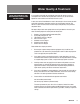
Water Quality & Treatment REDUCE SCALE PROBLEMS BY USING AND MAINTAINING A WATER SOFTENER FOR YOUR STEAMER! It is essential that the boiler be supplied with water that will not form scale at an unacceptable rate. The boiler was engineered to minimize scale, but its formation depends on water hardness and how much the unit is used. In some areas of the United States the water is low enough in mineral content to avoid scale build-up. However, most water supplies carry heavy loads of minerals.
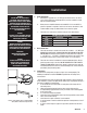
Installation WARNING MAKING ANY ELECTRICAL OR MECHANICAL CHANGE IN THE UNIT WITHOUT PRIOR APPROVAL WILL VOID ALL WARRANTIES. WHEN THE UNIT IS RECEIVED, IMMEDIATELY INSPECT IT FOR EXTERNAL OR INTERNAL DAMAGE. REPORT ANY DAMAGE TO THE FREIGHT CARRIER. After inspection, keep the unit in its shipping container until it is installed. It can be installed on combustible and non-combustible floors.
Installation WARNING THE UNIT MUST BE INSTALLED BY PERSONNEL WHO ARE QUALIFIED TO WORK WITH ELECTRICITY AND PLUMBING. IMPROPER INSTALLATION CAN CAUSE INJURY TO PERSONNEL AND/OR DAMAGE TO THE EQUIPMENT. THE UNIT MUST BE INSTALLED IN ACCORDANCE WITH ALL APPLICABLE CODES. 2. CAUTION SHIPPING STRAPS ARE UNDER TENSION. THEY CAN SNAP BACK VIOLENTLY AND CAUSE INJURY WHEN CUT.
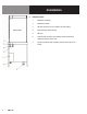
Installation 5. 8 OM-E-SB Utility Connections 1. Cold water (untreated). 2. Cold water (treated). 3. Hot water (for faucet on 36” and wider units with kettles). 4. Steam outlet (for power take-off). 5. Not used. 6. Drain (for boiler, steamers and condenser spray). Also for kettle condensate and sink where used. 7. Electrical (conduit through underside, terminals at the right on the inside).
Initial Start-Up After the unit has been installed, test it to ensure that it is operating properly. 1. Remove literature and packing material from the interior and exterior of the unit. 2. Make certain the water supply is turned on. 3. Turn on electrical power to the unit. 4. Turn the on/off switch on the cabinet front panel to the “ON” position: • The boiler drain valve will close and the unit will fill with water. • When the water level reaches the “mid” probe, the red RESET light will come on.
Operation WARNING ALL POTENTIAL USERS OF THE EQUIPMENT SHOULD BE TRAINED IN SAFE AND CORRECT OPERATING PROCEDURES. A. Controls Operating controls are located on the front panel of the unit. a. The on/off switch starts the unit or shuts it off. b. The RESET indicator lights to show that the boiler has filled with water and that the heater element contactors can close. c. The start switch (momentary) closes the heater element contactors.
Operation WARNING ANY POTENTIAL USER OF THE EQUIPMENT SHOULD BE TRAINED IN SAFE AND CORRECT OPERATING PROCEDURES. WARNING WHEN YOU OPEN THE DOOR, STAY AWAY FROM THE STEAM COMING OUT OF THE UNIT. THE STEAM CAN CAUSE BURNS. B. Operating Procedure 1. Turn on the water supply to the unit. 2. Turn on electrical power to the unit. 3. Turn the on/off switch on the front of the cabinet to “ON.” a. The boiler drain valve will close and the unit will fill with water. b.
Sequence of Operation CAUTION ESCAPING STEAM MAY CAUSE SEVER BURNS. STAY AWAY FROM THERMOSTATIC AIR VENT AND PRESSURE RELIEF VALVES. When electrical power is turned on to the unit, the following happens: • The drain valve closes • The water valve opens • The unit fills with water As the boiler fills, the water is detected by two probes. The first of these is the “mid” probe, which activates the RESET light. The second (“hi” probe) is reached when the boiler is full, and shuts off the water supply.
Steamer Compartment Cleaning WARNING DISCONNECT THE POWER SUPPLY BEFORE CLEANING THE OUTSIDE OF THE STEAMER. KEEP WATER AND CLEANING SOLUTIONS OUT OF CONTROLS AND ELECTRICAL COMPONENTS. NEVER HOSE OR STEAM CLEAN ANY PART OF THE UNIT. To keep your Steamer in proper working condition, clean the unit each day. This regular cleaning will reduce the effort required to clean the cavities. A. 1. 2. 3.
Boiler Cleaning WARNING WATER AND VALVES MAY BE VERY HOT, AND MAY CAUSE BURNS. PROTECT HANDS FROM HOT SURFACES AND WATER. WARNING USE SAFETY GLASSES AND RUBBER GLOVES AS RECOMMENDED BY DE-LIMING AGENT MANUFACTURER. CAUTION DO NOT USE A CLEANING OR DE-LIMING AGENT THAT CONTAINS SULFAMIC ACID OR ANY CHLORIDES, INCLUDING HYDROCHLORIC ACID (HCL). IF THE CHLORIDE CONTENT OF ANY PRODUCT IS UNCLEAR, CONSULT THE MANUFACTURER. The manual drain valve is located under the boiler.
Cleaning WARNING SOLUTION AND VALVES WILL BE VERY HOT, AND MAY CAUSE BURNS. PROTECT HANDS FROM HOT SURFACES AND CONTINUE TO USE PROTECTIVE GLOVES. 13. Set steamer timers for 10 minutes. 14. When steamer timers sound, turn them to OFF and open the doors. 15. When the fans have stopped, remove fan baffle partitions using protective gloves, and rinse with clean water. 16. Completely wipe out steamer chambers using a degreaser and nylon pad, if necessary. Rinse thoroughly with clean water. 17.
Steamer Maintenance WARNING BEFORE REPLACING ANY PART TURN OFF THE ELECTRICAL POWER TO THE UNIT. DEATH OR INJURY COULD RESULT FROM CONTACT WITH HIGH VOLTAGE. The Steamer is designed for minimum maintenance, and no user adjustments should be necessary. Certain parts may need replacement after prolonged use. If there is a need for service, only Authorized Service Representatives should do the work.
Maintenance WARNING USE ONLY MANUFACTURER-SUPPLIED PARTS. USING SUBSTITUTE, UNAUTHORIZED OR “GENERIC” PARTS CAN CAUSE BODILY INJURY TO THE OPERATOR AND DAMAGE THE EQUIPMENT. WARNING DO NOT EXPOSE SKIN TO ESCAPING STEAM. SEVERE BURNS MAY RESULT. Your boiler is designed to minimize maintenance, but certain parts may need to be replaced after prolonged use. For the most part, no user adjustments should be necessary. If a need for service arises, only Authorized Representatives should perform the work.
Troubleshooting Do not operate the unit if it malfunctions or has damaged or broken parts. Steam boilers are designed to operate smoothly and efficiently when maintained properly. However, the following is a list of checks to make if there is a problem. Electrical schematics are provided in this manual, and inside the unit electrical enclosure. IF THE ITEM ON THE LIST IS MARKED WITH (X), THE WORK SHOULD ONLY BE DONE BY A FACTORY-AUTHORIZED SERVICE REPRESENTATIVE.
Troubleshooting SYMPTOM Boiler builds pressure but shuts down. RESET light comes on. WHO WHAT TO CHECK User a. Is the water level below the “mid” water level probe? Verify that the water supply is sufficient to maintain the water level at or above the “mid” water level probe. Authorized b. Is the operating pressure switch defective? No adjustment is Service Rep Only allowed. Replace the switch if defective.
Steamer Cavity 20 OM-E-SB Parts List
Parts List Steamer Cavity Key Description Part # Key Description Part # 1 UPPER CAVITY DRAIN HOSE 088847 21 BRACKET, TRANSFORMER MTG - SE - 480V 102287 2 MOTOR ASSEMBLY 096740 22 RUBBER PAD - SE - 480V 102292 3 TIMER 096826 23 TRANSFORMER, 230V - SE - 480V 101111 4 KNOB, TIMER 123100 24 SCREW, 1/4-20 X 2-1/4 - SE - 480V 119836 5 PC BOARD, HY-PLUS LIGHT AND TIMER 130457 25 CIRCUIT BREAKER, 2 AMP - SE - 480V 119836 6 BRACKET, BOARD MTG 096888 26 WIRE, 4” - SE - 480V
Parts List Motor/Fan Assembly Key Description Part # 1 MOTOR 096739 2 SLINGER WASHER 096831 3 MOTOR MOUNTING PLATE 094134 4 SHAFT SEAL 096868 5 PLATE SEAL HOLDER 096752 22 OM-E-SB
Parts List Sheet Metal & Doors Key Description Part # 1 COVER, RIGHT SIDE (6-PAN) 143778 1 COVER, RIGHT SIDE (10-PAN) 159866 2 COVER, LEFT SIDE (6-PAN) 123184 2 COVER, LEFT SIDE (10-PAN) 159867 3 COVER ASSEMBLY, TOP 123182 4 SCREW, 10-32 X 3/8 TRUSS HEAD 004173 5 RETAINER, TOP 123156 6 SCREW, 8-32 X 3/8 SLOTTED HEX HEAD 004173 7 DOOR HANDLE 070123 8 DOOR HINGE (6-PAN) 130868 8 DOOR HINGE (10-PAN) 125928 9 OUTER DOOR (6-PAN) 130858 9 OUTER DOOR (10-PAN) 125922 OM-E
Parts List Door & Cavity Hardware Key Description Part # 1 DOOR GASKET (6-PAN) 094147 1 DOOR GASKET (10-PAN) 125907 2 DOOR HANDLE 070123 3 DOOR CAM 074252 4 MAGNET ASSEMBLY 069762 5 U-CHANNEL ASSY. (6PAN) (INCL. DOOR SPRING 078911) 094144 5 U-CHANNEL ASSY. (10PAN) (INCL.
Drain Box w/Spray Condenser Key Description Parts List Part # 1 SOLENOID VALVE (SPRAY CONDENSER) 099221 2 HOSE D “ ID X 8” LONG 099282B 3 RUBBER FLAP 099213 4 SPACER 099212 5 HOSE, OUTLET 1 “ID X 3” LONG 099280B 6 ANCHOR COUPLING, D” NPT N89267 OM-E-SB 25
Parts List Boiler Electrical Controls Key Description Part # 1 2 WATER LEVEL BOARD, SINGLE WATER LEVEL BOARD, DOUBLE TRANSFORMER 208/240V PRIMARY/24V SECONDARY, 75VA CONTACTOR FUSEHOLDER FUSE GROUND TERMINAL TERMINAL BLOCK LIGHT AMBER LIGHT RED LAMP RESET PRESSURE RELIEF VALVE DRAIN VALVE SWITCH, RESET SWITCH, POWER PRESSURE GAUGE WATER LEVEL PROBE WATER LEVEL PROBE EXTENSION SIGHT GLASS THERMOSTAT RELAY, CUTOUT RELAY, DPDT 24VAC GASKET, ELEMENT 122192 116016 3 4 5 6 7 8 9 10 11 12 13 14 15 16 17 18
Steamer Cavities Electrical Schematic OM-E-SB 27
Boiler 28 OM-E-SB Electrical Schematic
Service Log Model No: Purchased From: Serial No: Location: Date Purchased: Date Installed: Purchase Order No: For Service Call: Date Maintenance Performed Performed By OM-E-SB 29
Service Log Model No: Purchased From: Serial No: Location: Date Purchased: Date Installed: Purchase Order No: For Service Call: Date 30 OM-E-SB Maintenance Performed Performed By
OM-E-SB 31
BLODGETT OVEN COMPANY www.blodgett.