ZEPHAIRE-G CONVECTION OVEN INSTALLATION -- OPERATION -- MAINTENANCE ZEPHAIRE-G FOURS À CONVECTION MANUEL D’INSTALLATION -- FONCTIONNEMENT -- ENTRETIEN BLODGETT OVEN COMPANY www.blodgett.com 44 Lakeside Avenue, Burlington, Vermont 05401 USA Telephone (800) 331-5842, (802) 860-3700 Fax: (802)864-0183 PN 90139 Rev J (6/01) E 2001 --- G.S.
IMPORTANT WARNING: IMPROPER INSTALLATION, ADJUSTMENT, ALTERATION, SERVICE OR MAINTENANCE CAN CAUSE PROPERTY DAMAGE, INJURY OR DEATH. READ THE INSTALLATION, OPERATING AND MAINTENANCE INSTRUCTIONS THOROUGHLY BEFORE INSTALLING OR SERVICING THIS EQUIPMENT AVERTISSEMENT: UNE INSTALLATION, UN AJUSTEMENT, UNE ALTÉRATION, UN SERVICE OU UN ENTRETIEN NON CONFORME AUX NORMES PEUT CAUSER DES DOMMAGES À LA PROPRIÉTE, DES BLESSURES OU LA MORT.
THE REPUTATION YOU CAN COUNT ON UNE RÉPUTATION SUR LAQUELLE VOUS POUVEZ COMPTER For over a century and a half, The Blodgett Oven Company has been building ovens and nothing but ovens. We’ve set the industry’s quality standard for all kinds of ovens for every foodservice operation regardless of size, application or budget.
Model/Modèl: Your Service Agency’s Address: Adresse de votre agence de service: Serial Number/Numéro de série: Your oven was installed by/ Installateur de votre four: Your oven’s installation was checked by/ Contrôleur de l’installation de votre four:
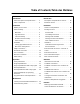
Table of Contents/Table des Matières Introduction Introduction Oven Description and Specifications . . . . 2 Description et Spécifications du Four . . . . 26 Oven Components . . . . . . . . . . . . . . . . . . . . 3 Éléments du Four . . . . . . . . . . . . . . . . . . . . . 27 Installation Installation Delivery and Location . . . . . . . . . . . . . . . . . 4 Livraison et Implantation . . . . . . . . . . . . . . . 28 Oven Assembly . . . . . . . . . . . . . . . . . . . . . . 5 Montage du Four . .
Introduction Oven Description and Specifications Cooking in a convection oven differs from cooking in a conventional deck or range oven since heated air is constantly recirculated over the product by a fan in an enclosed chamber. The moving air continually strips away the layer of cool air surrounding the product, quickly allowing the heat to penetrate. The result is a high quality product, cooked at a lower temperature in a shorter amount of time.
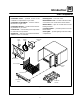
Introduction Oven Components Combustion Cover --- provides access to the combustion compartment on gas ovens. Rack Supports --- hold oven racks. Blower Wheel Cover --- located on the back interior wall of the oven. Protects the blower wheel. Combustion Compartment --- contains combustion burners on gas ovens. Blower Wheel --- spins to circulate hot air in the baking chamber. Combustion Burners --- provide heat to the baking chamber on gas ovens.
Installation Delivery and Location DELIVERY AND INSPECTION It is essential that an adequate air supply to the oven be maintained to provide a sufficient flow of combustion and ventilation air. All Blodgett ovens are shipped in containers to prevent damage. Upon delivery of your new oven: D D D Inspect the shipping container for external damage. Any evidence of damage should be noted on the delivery receipt which must be signed by the driver. Uncrate the oven and check for internal damage.
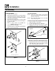
Installation Oven Assembly NSF BOLTS any holes in stacked units not used for mounting stacking brackets. 1. Locate the 5/16” bolts that were shipped with the oven. 2. Install the bolts as shown in Figure 3. D These bolts are required by NSF to block any exposed hole on the back of an oven. This includes: D any unit, single or stacked, without a back panel.
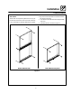
Installation Oven Assembly CASTER ASSEMBLY LEG ATTACHMENT 1. Lay the oven on its back. 2. Align the threaded stud in each leg with the nut located inside each bottom corner of the oven frame. Turn the legs clockwise and tighten to the nearest full turn. 3. Align the two leg plate holes in each leg with those in the oven bottom. Secure each leg using two 1/2” bolts. NOTE: If using casters see CASTER ASSEMBLY before proceeding. 4. Tip the oven up on the legs. 5.
Installation Oven Assembly DOUBLE SECTION ASSEMBLY 3. Attach the stacking brackets using the remaining 5/16” bolts shipped with the ovens. 4. Drill a clearance hole for a 5/16” bolt in the angle iron of the old style oven. Use the holes in the stacking brackets as a pilot. 5. Attach the stacking brackets to the old style oven with the 5/16” bolts and nuts provided in the kit. 6. Attach the flue connector. NOTE: Old style ovens refer to units with painted exposed rear angle.
Installation Ventilation CANOPY TYPE EXHAUST HOOD On gas models the installation of a proper ventilation system cannot be over emphasized. This system removes unwanted vapors and products of combustion from the operating area. A mechanically driven, canopy type exhaust hood is the preferred method of ventilation. The hood should be sized to completely cover the equipment plus an overhang of at least 6” (15 cm) on all sides not adjacent to a wall.
Installation Ventilation DIRECT FLUE ARRANGEMENT Installing the draft hood When the installation of a mechanically driven exhaust hood is impractical the oven may be vented by a direct flue arrangement. Ovens ordered for direct venting are supplied with a draft hood. Install the draft hood as follows: 1. Place the draft hood over the flue connector. See Figure 9. 2. Secure both ends with the sheet metal screws provided. WARNING!! It is essential that the direct flue be installed as follows.
Installation Utility Connections --- Standards and Codes THE INSTALLATION INSTRUCTIONS CONTAINED HEREIN ARE FOR THE USE OF QUALIFIED INSTALLATION AND SERVICE PERSONNEL ONLY. INSTALLATION OR SERVICE BY OTHER THAN QUALIFIED PERSONNEL MAY RESULT IN DAMAGE TO THE OVEN AND/OR INJURY TO THE OPERATOR.
Installation Gas Connection GAS PIPING A properly sized gas supply system is essential for maximum oven performance. Piping should be sized to provide a supply of gas sufficient to meet the maximum demand of all appliances on the line without loss of pressure at the equipment. Example: NOTE: BTU values in the following example are for natural gas. You purchase a Zephaire-G convection oven to add to your existing cook line. 1. Add the BTU rating of your current appliances.
Installation Gas Connection PRESSURE REGULATION AND TESTING Zephaire-G ovens are rated at 60,000 BTU/Hr. (17.6 kW) (63 MJ) per section. Each oven has been adjusted at the factory to operate with the type of gas specified on the rating plate. DO NOT INSTALL AN ADDITIONAL REGULATOR WHERE THE OVEN CONNECTS TO THE GAS SUPPLY UNLESS THE INLET PRESSURE IS ABOVE MAXIMUM. Inlet Pressure Natural Propane Min Max Min Max W.C. 7.0 10.5 11.0 13.0 kPa 1.43 2.61 2.74 3.
Installation Gas Connection GAS HOSE RESTRAINT If the oven is mounted on casters, a commercial flexible connector with a minimum of 3/4” (1.9 cm) inside diameter must be used along with a quick connect device. The restraint, supplied with the oven, must be used to limit the movement of the unit so that no strain is placed upon the flexible connector. With the restraint fully stretched the connector should be easy to install and quick connect. The restraint (ie: heavy gauge cable) should be 1,000 lb.
Installation Electrical Connection Wiring diagrams are located in the control compartment and on the back of the oven. WARNING!! This appliance is equipped with three prong grounding type plug for your protection against shock hazard and should be plugged directly into a properly grounded three prong receptacle. DO NOT cut or remove the grounding prong from this plug. This oven is supplied for connection to 115 volt grounded circuits.
Installation Initial Startup The following is a check-list to be completed by qualified personnel prior to turning on the appliance for the first time. j Open the manual shut-off valve at the rear of the oven. j Remove the control panel and combustion covers. j Turn the combination valve’s manual shut-off to the on position. j Turn the selector switch to Cook, and the thermostat to 500_F (260_C). The oven main burner lights, and the Oven Ready Light comes on.
Operation Safety Information THE INFORMATION CONTAINED IN THIS SECTION IS PROVIDED FOR THE USE OF QUALIFIED OPERATING PERSONNEL. QUALIFIED OPERATING PERSONNEL ARE THOSE WHO HAVE CAREFULLY READ THE INFORMATION CONTAINED IN THIS MANUAL, ARE FAMILIAR WITH THE FUNCTIONS OF THE OVEN AND/OR HAVE HAD PREVIOUS EXPERIENCE WITH THE OPERATION OF THE EQUIPMENT DESCRIBED. ADHERENCE TO THE PROCEDURES RECOMMENDED HEREIN WILL ASSURE THE ACHIEVEMENT OF OPTIMUM PERFORMANCE AND LONG, TROUBLE-FREE SERVICE.
Operation Single Speed Blower CONTROL DESCRIPTION 1 ON MAN OFF AUTO BLOWER COOL DOWN 1. BLOWER ON/OFF SWITCH --- Controls the operation of the blower. If the blower switch is in the OFF position the oven will be turned off. 2. COOL DOWN SWITCH --- When the switch is in the AUTO position, the oven can be used to cook. When the switch is in the MAN position, the oven is cooling down for the next bake. 3. OVEN READY LIGHT - When lit indicates burners are operating.
Operation Single Speed Blower with Cavity Lights CONTROL DESCRIPTION 1 2 ON ON MAN OFF OFF AUTO LIGHTS BLOWER 1. CAVITY LIGHTS ON/OFF --- Operates the oven cavity lights. 2. BLOWER ON/OFF SWITCH --- Controls the operation of the blower. If the blower switch is in the OFF position the oven will be turned off. 3. COOL DOWN SWITCH --- When the switch is in the AUTO position, the oven can be used to cook. When the switch is in the MAN position, the oven is cooling down for the next bake. 4.
Operation Dual Speed Blower CONTROL DESCRIPTION 1 HI MAN OFF LOW BLOWER 1. BLOWER HI/LO/OFF SWITCH --- Controls the operation of the blower. If the blower switch is in the OFF position the oven will be turned off. 2. COOL DOWN SWITCH --- When the switch is in the AUTO position, the oven can be used to cook. When the switch is in the MAN position, the oven is cooling down for the next bake. 3. OVEN READY LIGHT - When lit indicates burners are operating.
Operation Dual Speed Blower with Cavity Lights CONTROL DESCRIPTION 1 ON MAN OFF OFF 2 HI LOW LIGHTS BLOWER 1. CAVITY LIGHTS ON/OFF --- Operates the oven cavity lights. 2. BLOWER HI/LO/OFF SWITCH --- Controls the operation of the blower. If the blower switch is in the OFF position the oven will be turned off. 3. COOL DOWN SWITCH --- When the switch is in the AUTO position, the oven can be used to cook. When the switch is in the MAN position, the oven is cooling down for the next bake. 4.
Operation General Guidelines for Operating Personnel COOK TIMES AND TEMPERATURES OPERATING TIPS Preheating the oven Pans and Racks Always preheat the oven before baking or roasting. We recommend preheating 50_F (10_C) above the cook temperature to offset the drop in temperature when the doors are opened and cold product is loaded into the oven. Set the thermostat to the cook temperature after the product is loaded. Product or pan height determines how many racks are used.
Operation Suggested Times and Temperatures Product Temperature Time # Shelves Meats Hamburger Patties (5 per lb) Steamship Round (80 lb. quartered) Standing Rib Choice (20 lbs, trimmed, rare) Banquet Shell Steaks (10 oz. meat) Swiss Steak after Braising Baked Stuffed Pork Chop Boned Veal Roast (15 lbs.) Lamb Chops (small loin) Bacon (on racks in 18” x 26” pans) 400_F (205_C) 275_F (135_C) 235_F (115_C) 450_F (235_C) 275_F (135_C) 375_F (190_C) 300_F (150_C) 400_F (205_C) 400_F (205_C) 8-10 mins.
Maintenance Cleaning and Preventative Maintenance CLEANING THE OVEN PREVENTATIVE MAINTENANCE Painted and stainless steel ovens may be kept clean and in good condition with a light oil. 1. Saturate a cloth, and wipe the oven when it is cold. 2. Dry the oven with a clean cloth. The best preventative maintenance measures are, the proper installation of the equipment and a program for routinely cleaning the ovens.
Maintenance Troubleshooting Guide POSSIBLE CAUSE(S) SUGGESTED REMEDY SYMPTOM: Oven will not fire. S S S S S Gas turned off. S S S S S Oven not plugged in. Power switch on the control panel is off. Control set below ambient temperature. Doors are open. Turn the gas valve to ON. Plug in electrical supply cord. Set the control panel to COOK or OVEN ON. Set to desired cook temperature. Close doors. SYMPTOM: Oven does not come to ready. S The oven has not reached preheat temperature.
Zephaire-G Fours à Convection Manuel D’Installation --- Utilisation --- Entretien 25
Introduction Description et Spécifications du Four La cuisson dans un four à convection diffère de la cuisson dans un four de cuisine ordinaire en ce sens que de l’air chaud circule en permanence autour de l’aliment cuit, sous l’effet d’un ventilateur enfermé dans une enceinte spéciale. Le mouvement continu de l’air, en éliminant constamment la couche d’air froid qui se formerait autrement autour de l’aliment, permet la pénétration plus rapide de la chaleur.
Introduction Éléments du Four Porte de Combustion --- permet l’accès au compartiment de combustion des fours à gaz. Compartiment de Combustion --- contient les brûleurs des fours à gaz. Brûleurs --- fournissent la chaleur à la cavité des fours à gaz. Panneau de Contrôle --- contient les câblages et les éléments permettant de contrôler le fonctionnement du four. Grilles de four --- cinq grilles sont fournies en équipement standard. Des grilles supplémentaires sont disponibles.
Installation Livraison et Implantation LIVRAISON ET INSPECTION Tous les fours sont expédiés en conteneurs. A la réception de votre four Blodgett vous devez: D D Vérifier que les emballages ne sont pas abimés. Toute défection dans l’emballage doit être notée sur l’accusé de reception de la marchandise; celui-ci doit être signé par le chauffeur. Sortir le four de son emballage et vérifier son bon état.
Installation Montage du Four BOULONS NSF La NSF exige la pose de boulons dans tous les trous vides situés à l’arrière du four, notamment dans les cas suivants : D D 1. Repérez les boulons de 5/16 po expédiés avec le four. 2. Posez les boulons comme l’illustre la Figure 19. tout appareil, seul ou superposé, ne comportant aucun panneau arrière. tout trou d’appareils superposés ne servant pas à maintenir une ferrure de montage superposé.
Installation Montage du Four ASSEMBLAGE DES PIEDS 1. Coucher le four sur le dos. 2. Alignez le goujon fileté du pied sur le trou de vis prévu dans le coin avant du fond de caisse. Vissez le pied, dans le sens des aiguilles d’une montre, jusqu’au dernier tour complet possible. 3. Alignez les deux orifices de la plaque du pied sur les trous prévus au bas du four. Fixez le pied à l’aide de deux boulons de 12.7 mm (1/2 po). REMARQUE:Si des roulettes sont utilisées, voir MONTAGE DES ROULETTES avant de continuer.
Installation Montage du Four MONTAGE DE LA SECTION DOUBLE REMARQUE:Les vieux modèles de fours sont ceux qui ont un cadre arrière peinturé. Les nouveaux modèles de fours sont ceux avec un cadre arrière enfermé en acier. Les instructions suivantes sont applicable a l’assemblage de deux nouveaux modèles de fours. 1. Fixez les pieds de courte longueur au bas de la section inférieure comme décrit. 2. Posez la section supérieure par-dessus la section inférieure. 3.
Installation Ventilation Un système de ventilation planifié et installé est absolument nécessaire car il permet un bon fonctionnement du four tout en débarassant la surface de travail des buées et résidus de combustion. HOTTE D’ÉVACUATION TYPE VOÛTE Il y a deux méthodes de ventilation acceptables pour le four: La hotte doit être conçue pour couvrir la totalité de l’appareil à ventiler avec en plus un surplomb se 15 cm (6”) de chaque côté de l’appareil non adjacent au mur.
Installation Ventilation EN PRISE DIRECTE Installation de la hotte de tirage Quand l’installation d’une hotte aspirante mécanique est impossible ou peu pratique à réaliser, on peut ventiler le four au moyen d’une installation en prise directe. Les four commandés pour la ventilation directe sont fournis avec une hotte de tirage. Installer la hotte de tirage comme suit : AVERTISSEMENT!! Quand on utilise un système à prise directe il faut absolument suivre le schéma.
Installation Branchements de Service --- Normes et Codes LES CONSEILS D’INSTALLATION ET D’ENTRETIEN CONTENUS DANS CE MANUEL NE S’ADRESSENT QU’Á UN PERSONNEL QUALIFIÉ. UN PERSONNEL NON QUALIFIE PEUT SE BLES SER ET/OU ABÎMER LE FOUR LORS DE SON INSTALLATION ET/OU SON ENTRETIEN.
Installation Branchement de Gaz CONDUIT DE GAZ Un système d’alimentation en gaz de bon calibre est essentiel pour obtenir le meilleur rendement du four. Les conduits doivent être calibrés pour fournir suffisamment de gaz pour alimenter tous les appareils sur le conduit sans perte de pression à l’équipement.
Installation Branchement de Gaz RÉGLAGE ET TEST DE PRESSION Chaque section du four opère à régime nominal de 60,000 BTU/heure (17.6 kW) (63 MJ). Tous les fours sont réglés en usine en fonction du type de gaz spécifié sur la plaque signalétique. Pression à l’entrée Gaz Naturel Gaz Propane Min Max Min Max W.C. 7.0 10.5 11.0 13.0 kPa 1.43 2.61 2.74 3.
Installation Branchement de Gaz RETENUE DU TUYAU DE GAZ Si le four est monté sur roulettes, un connecteur commercial flexible ayant un diamètre intérieur minimum de 1,9 cm (3/4”) doit être utilisé avec un dispositif de connexion rapide. La retenue, fournie avec le four, doit servir à limiter les mouvements de l’unité de façon qu’aucune tension ne soit placée sur le connecteur flexible. Quand la retenue est entièrement étendue, le connecteur doit être facile à installer et à connecter rapidement.
Installation Raccordement Électrique Les diagrammes de câblage se trouvent dans le coffret de commande et à l’arrière du four. AVERTISSEMENT!! Pour votre protection contre les risques d’électrocution, cet appareil est doté d’une fiche a trois broches avec fil de terre et doit etre branché directement dans une prise a trois trous adéquatement mise a la terre. Ne coupez ou ne retirez en aucun cas la broche de terre de la fiche. Ce four est équipé pour connexion sur un circuit de prise de terre de 115 volts.
Installation Mise en Marche Initiale Les points de la liste qui suit doivent être contrôlés par un personnel qualifié avant la première mise en marche de l’appareil. j Ouvrez la vanne d’arrêt manuelle combinée à l’arrière du four. j Enlevez les couvercles du tableau de commande et de combustion. j Tourner la vanne d’arrêt manuel à combinaison sur la position marche. j Mettez le sélecteur en position Cook (cuisson) et la temperature à 260_C (500_F).
Utilisation Informations de Sécurité Que faire en cas de panne de secteur : Fermer tous les interrupteurs. D NE PAS tenter d’utiliser le four avant que l’électricité soit revenue. LES INFORMATIONS CONTENUES DANS CETTE SECTION SONT DESTINÉES AU PERSONNEL QUALIFIÉ APPELÉ A UTILISER LE FOUR.
Utilisation Soufflerie Une Vitesse DESCRIPTION DES COMMANDES 1 ON MAN OFF AUTO BLOWER COOL DOWN 1. INTERRUPTEUR MARCHE/ARRÊT DE SOUFFLERIE --- contrôle la mise en marche de la soufflerie. Si l’interrupteur est en position ARRÊT (OFF) le four s’arrête. 2. INTERRUPTEUR REFROIDIR --- en position AUTO, le four peut être utilisé pour cuire. Si l’interrupteur est en position MANuelle, le four se refroidit avant la prochaine cuisson. 3.
Utilisation Soufflerie Une Vitesse avec Lumières de Cavité DESCRIPTION DES COMMANDES 1 2 ON ON MAN OFF OFF AUTO LIGHTS BLOWER 1. LUMIÈRES DE CAVITÉ MARCHE/ARRÊT --actionne les lumières dans la cavité du four. 2. INTERRUPTEUR MARCHE/ARRÊT DE SOUFFLERIE --- contrôle la mise en marche de la soufflerie. Si l’interrupteur est en position ARRÊT (OFF) le four s’arrête. 3. INTERRUPTEUR REFROIDIR --- en position AUTO, le four peut être utilisé pour cuire.
Utilisation Soufflerie Deux Vitesses DESCRIPTION DES COMMANDES 1 HI MAN OFF LOW BLOWER 1. INTERRUPTEUR SOUFFLERIE HAUT/BAS/ ARRÊT --- contrôle le fonctionnement de la soufflerie. Si l’interrupteur de la soufflerie est en position ARRÊT (OFF), le four est mis à l’arrêt. 2. INTERRUPTEUR REFROIDIR --- en position AUTO, le four peut être utilisé pour cuire. Si l’interrupteur est en position MANuelle, le four se refroidit avant la prochaine cuisson. 3.
Utilisation Soufflerie Deux Vitesses avec Lumières de Cavité DESCRIPTION DES COMMANDES 1 ON MAN OFF OFF 2 HI LOW LIGHTS BLOWER 1. LUMIÈRES DE CAVITÉ MARCHE/ARRÊT --actionne les lumières dans la cavité du four. 2. INTERRUPTEUR SOUFFLERIE HAUT/BAS/ ARRÊT --- contrôle le fonctionnement de la soufflerie. Si l’interrupteur de la soufflerie est en position ARRÊT (OFF), le four est mis à l’arrêt. 3. INTERRUPTEUR REFROIDIR --- en position AUTO, le four peut être utilisé pour cuire.
Utilisation Consignes Générales à l’Intention des Utilasateurs TEMPS ET TEMPÉRATURES DE CUISSON un maximum de 10 plaques à petits pains de 18 x 26 po (457 x 660 mm). Préchauffage du four Toujours préchauffer le four avant de cuire ou de rôtir. Nous recommandons un préchauffage de 10_C (50_F) supérieur à la température de cuisson pour compenser la chute de température quand les portes sont ouvertes et qu’un produit froid est chargé dans le four.
Utilisation Durées et Températures Suggérées Aliment Température Durée Étagères Viandes Hamburgers (5 pâtés/lb) Gîte (80 lbs, en quartiers) Côte de choix (20 lbs, dégraissé, saignant) Contre-filet (portions de 10 oz) Steak suisse après braisage Côtelette de porc farcie Rôti de veau désossé (15 lbs) Côtelettes d’agneau (premières) Lard (sur grilles en plats de 18 x 26 po) 400_F (205_C) 275_F (135_C) 235_F (115_C) 450_F (235_C) 275_F (135_C) 375_F (190_C) 300_F (150_C) 400_F (205_C) 400_F (205_C) 8-10 m
Entretien Nettoyage et Entretien Préventif NETTOYAGE DES FOURS ENTRETIEN PRÉVENTIF Les fours peints et en acier inoxydable peuvent être conservés en bon état si on les nettoie avec une huile légère. Il doit être assuré par une installation initiale correcte et un programme de nettoyage régulier des fours. 1. Imprégner un chiffon de cette huile et frotter le four lorsque celui-ci est froid. 2. L’essuyer avec un chiffon propre et sec.
Entretien Guide de Détection des Pannes CAUSE(S) PROBABLE(S) SUGGESTION SYMPTOME: Le four ne s’allume pas. S Le gaz est fermé. S Tourner la vanne de gaz sur ON (MARCHE). S Le four n’est pas branché. S Brancher le fil dans la prise. S L’interrupteur électrique du paneau de contrôle S Régler le panneau de contrôle sur COOK (CUISest sur arrêt. SON) ou OVEN ON (FOUR MARCHE). S Contrôle réglé au-dessous de la température S Régler la température désirée. ambiante. S Portes ouvertes. S Fermer les portes.
INSERT WIRING DIAGRAM HERE PLACER SCHÉMA DE CÂBLAGE ICI