
Repair manual

MT3855
3
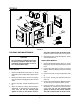
REPAIRING THE ELECTRONIC IGNITION
SYSTEM
Flame Sensing Current Maintenance:
The flame sensor is made of carbon steel and subĆ
ject to contamination and oxidation buildup. Any
buildup on the sensor can add enough resistance
to drop the signal below the required minimum.
Carbon and oxidation can also build up on the pilot
hood. The pilot hood is part of the circuit and must
be kept as clean as the flame sensor.
1. Clean the flame sensor with steel wool or an
emery cloth.
2. Clean the pilot hood with a small wire brush to
remove any carbon or oxidation buildup.
Flame Sensor Replacement:
If the ceramic portion of the flame sensor is broken
or if the contamination is extensive, the flame senĆ
sor may have to be replaced.
CAUTION!
Shut off all gas to the appliance by closing
the shutoff valve in the supply line to that
appliance. Disconnect the power supply
to prevent electrical shock or possible
damage to the equipment.
1. Disconnect the sensing probe cable from the
old sensing probe.
2. Remove the old sensing probe from the pilot
burner.
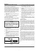
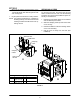
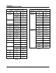
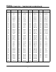
3. Check the length of dimension B to be sure the
correct replacement probe is being used. See
FIGURE 2.
4. Compare the sensing probe rod lengths, diĆ
mension A. If required, trim the length of the
Y75 rod being installed to the same length as
the sensing rod being replaced.
AB
FIGURE 2
5. Install the Y75 sensing probe into the pilot
burner. Reconnect the sensing probe cable.
The connections to the sensing probe and
control terminal must be secure.
6. Restore the power and the gas supply to the
appliance.
7. IMPORTANT: Using a microammeter, check
the signal passing through the sensing probe.
8. If the microamp signal is marginal, trim the
flame sensing probe in increments of 1/8". Be
sure that there is still proper flame impingeĆ
ment on the flame sensing probe.
Flame must surround sensing probe tip for
approximately 1/2".
9. Observe at least three complete operating
cycles to see that all components are functionĆ
ing correctly.
Ground Connection
Another important requirement for proper operaĆ
tion is the existence of a good electrical ground beĆ
tween the pilot assembly and the ignition control.
This ground provides the path for sensing current
to return to the control, thereby completing the
sensing circuit.
In most systems we assume the pilot burner is
grounded back to the control through the pilot tubĆ
ing and gas valve. The gas valve would be
grounded to the ignition control when the control
is mounted on the valve. Controls that are not
mounted to a gas valve require a separate groundĆ
ing wire connecting the control to the pilot assemĆ
bly.
In some instances this ground can become weak
and cause a low sensing current signal. To assure
that a proper ground exists between the control
and pilot, a wire can be installed from one of the
ground terminals to the pilot bracket. This will asĆ
sure a strong ground and maintain a proper sensĆ
ing current signal.
Using a 1/4" female spade connector, connect one
end of the new wire to the ground strip on the igniĆ
tion control. Attach the other end of the wire to a
bolt or screw on the pilot burner bracket. Be sure
to use a wire with a high temperature rated insulaĆ
tion.