
Repair manual


MT3855
10
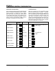
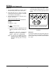
Warning: Circuit components are not at ground potential! Use only a nonĆmetallic or
insulated adjustment tool. Shock hazards may occur with conducting tools!
REMOVE RED PLUG FROM TOP OF DC MOTOR PRIOR TO OPERATING!
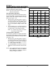
Line Neutral (VAC)
Regulation
Adjustment
Test
Points
Maximum Speed
Minimum Speed
Acceleration Adjustment
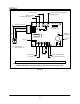
ACC MAX MIN
TORQ
Socket J1
Line Fuse
FL
REG
L N A1 A2
TB1
Speed Pot
Yellow or Violet (pin 12)
Blue (pin 8)
Ć
+
Torque (current) limiting adjustment
(DO NOT ADJUST)
FA
DIP Switch on
early models only
Switches 2,4,5,6,7
NOTE: Colors may vary
between early ovens.
Orange or Gray (pin 10)
Violet
Gray
Blue
ON
TP2
TP1
Line Hot (VAC)
Armature
Fuse
PM Motor
Armature
Power Line and Motor Ground
Barrier Terminal Block TB1
FIGURE 3