
Repair manual


MT3855
9
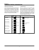
MOTOR CONTROL BOARD ADJUSTMENT
High/low speed motor control board adjustĆ
ment for 180 and 130 volt DC motors
NOTE: The motor control board is located on the
slide out control panel.
High Speed Motor Adjustment:
For closed loop systems follow Belt Speed VerificaĆ
tion through STEP 5 (see page 6). For open loop
systems follow Belt Speed Calibration through
STEP 2 (see page 7 or 8).
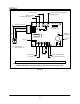
1. With the motor connected (make no open cirĆ
cuit voltage readings) measure the voltage at
the motor leads (A1 & A2 in FIGURE 3) on the
DC control board. If the voltage is not within 3
VDC of the specified voltage continue with
step 3.
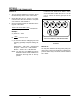
2. Turn the MAX trim pot counterĆclockwise to
lower and clockwise to raise the voltage until
it is within 3VDC of the specified voltage.
NOTE: For closed loop systems this adjustĆ
ment must be made quickly.
Low Speed Motor Adjustment:
For closed loop systems the computer automaticlĆ
ly proceeds to low speed. For open loop systems
continue Belt Speed Calibration through STEP 3
(see page 7 or 8).
1. With the motor connected (make no open cirĆ
cuit voltage readings) measure the voltage at
the motor leads on the DC control board (A1 &
A2 in FIGURE 3). If the voltage is not 26VDC
+/Ć 1 VDC, continue with step 3.
2. Turn the MIN SPEED pot clockwise to lower the
voltage and counterĆclockwise to raise the voltĆ
age.
NOTE: If any voltage adjustments were made hit
the CLEAR key to abort the calibration
mode. Reenter the calibration mode to
verify that voltage is locked in.
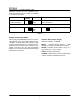
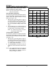
COMPUTERIZED OVENS
130 Volt System 180 Volt System
Model Low High Low High
MT1828 20 130 26 180
MT2136 20 130 26 180
MT3240 20 130 26 180
MT3270 26 130 26 180
MT3855 26 130 26 180
MT3870 26 130 26 130
NONĆCOMPUTERIZED OVENS
MT2136 20 130 26 180
MT3255 26 130 26 180
MT3270 26 130 26 180
MG3270 26 130
24 VDC SYSTEM
MT1820 3.0 21
TABLE 6