
Repair manual

MT3855
3
FOLDING CONVEYOR ASSEMBLY
For units manufactured after 11/14/95
The conveyor must be installed from the left side
(control box side) of the oven.
1. Unfold the conveyor while inserting it into the
support tracks. Be careful to avoid hitting the
emergency off switch on the side of the conĆ
trol box.
2. Insert the conveyor in beyond the normal restĆ
ing position.
3. Install the drive chain around the drive motor
sprocket and the conveyor sprocket.
4. Pull the conveyor back out of the oven until the
1/4Ć20 thumb screw can be installed through
the conveyor support and into the control box
bracket.
NOTE: If the mounting hole cannot be lined up or
the chain is too loose, the drive motor will
need to be repositioned.
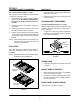
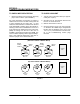
AIR PLATES
Verify that the proper air plates were received. InĆ
spect the orientation of the air plates. Refer to
FIGURE 6.
NOTE: Standard air plates shown. Alternate plates
available for some installations.
Left Air Plate
P/N M5767
Right Air Plate
P/N M5768
FIGURE 6
END PLUGS
1. Install the upper end plug support brackets at
both ends of the oven.
2. Install the upper and lower end plugs at both
ends of the oven.
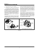
CONVEYOR BELT TENSIONERS
For units manufactured prior to 11/14/95.
Each tensioner installs between the idle end of the
conveyor (the side opposite the drive) and the
oven's body side.
1. Compress the spring by hand to engage the
tensioner pin with the hole in the oven's body
side. (Refer to FIGURE 7).
Oven Body Side
FIGURE 7
CRUMB PANS
1. Install the crumb pans under each end of the
conveyor.
MOUNT REMOTE CONTROL
1. Mount the remote control unit on a wall within
reach of the computer cables.
2. Connect the computer cables from the controlĆ
ler's rear connector to the connector located at
the rear of the oven.
FALSE FRONT (IF APPLICABLE)
Hang false front. Install door handle.