
Repair manual


MT3855
2
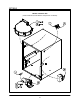
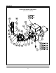
CONVEYOR RACK ASSEMBLIES
For units manufactured prior to 11/14/95.
1. Slide the drive side conveyor rack assembly
(with the sprocket on the end of the shaft) into
the support tracks.
2. Push until the end sprocket is inserted into the
control compartment.
3. Install the alignment bolt through the conveyor
and control box.
4. Slide the idle side conveyor rack assembly into
the support tracks from the exit end of the
oven.
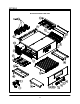
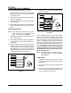
WIRE CONVEYOR BELT
NOTE: The conveyor belt has loops on all four
sides. The belt must be installed so the
loops travel as shown in FIGURE 4.
1. Thread the wire belt from the right side of the
oven, lower level first.
2. After pushing the belt through on the lower levĆ
el, leave about 12" (30.5 cm) hanging out on
the left side.
3. Take the remainder of the belt, loop it around
the right shaft, and push it through on the upĆ
per level. The two ends of the belt should be
approximately 6Ć9" (15Ć22 cm) past the left
shaft (right shaft if right to left travel is required)
on the upper level of the belt support.
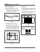
Side Belt Loops
Direction of
Travel
FIGURE 4
4. Install the inner and outer master links as
shown in FIGURE 5.
Master
Link
Direction of
Travel
FIGURE 5
Unless otherwise specified, the conveyor travel is
factory set for leftĆtoĆright operation when facing
the front of the oven. If a direction change is reĆ
quired, the polarity of the drive motor must be reĆ
versed. To change the polarity of the drive motor,
disconnect the oven from the power source and inĆ
terchange the black and white motor leads at the
D.C. Controller Board located within the control
box. If the polarity of the motor is changed to
rightĆtoĆleft belt travel, the conveyor belt must
be installed from the left side of the oven inĆ
stead of the right side.
NOTE: Change the air plates whenever the conĆ
veyor belt direction of travel is changed.
See FIGURE 6.
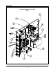
DRIVE CHAIN
1. Install the drive chain around the drive motor
and then around the sprocket on the conveyor
belt support.
2. Push the conveyor motor back to tighten the
drive chain.
3. Lock the motor into position by tightening the
four 1/4Ć20 hex head screws between the conĆ
veyor motor and the control box.