MT3855 CONVEYOR OVEN SERVICE AND REPAIR MANUAL BLODGETT OVEN COMPANY www.blodgettcorp.com 50 Lakeside Avenue, Box 586, Burlington, Vermont 05402 USA Telephone (802) 658Ć6600 Fax: (802)864Ć0183 PN M8402 Rev B (6/01) 1996 - G.S. Blodgett Corporation All rights reserved. Duplication of the information in this manual is prohibited without the consent of the Blodgett Service Department.
TABLE OF CONTENTS 1. INTRODUCTION Oven Specifications . . . . . . . . . . . . . . . . . . . . . . . . . . . . . . . . . . . . . . . . . . . . . . . . . . . . . . . . . . . . . . . Ventilation Requirements . . . . . . . . . . . . . . . . . . . . . . . . . . . . . . . . . . . . . . . . . . . . . . . . . . . . . . . Electrical Specifications . . . . . . . . . . . . . . . . . . . . . . . . . . . . . . . . . . . . . . . . . . . . . . . . . . . . . . . . Gas Specifications . . . . . . . . . . . . . . . . . . . .
TABLE OF CONTENTS Open Loop System - Twin Belt . . . . . . . . . . . . . . . . . . . . . . . . . . . . . . . . . . . . . . . . . . . . . . . . . Motor Control Board Adjustment . . . . . . . . . . . . . . . . . . . . . . . . . . . . . . . . . . . . . . . . . . . . . . . . Rerating the Appliance . . . . . . . . . . . . . . . . . . . . . . . . . . . . . . . . . . . . . . . . . . . . . . . . . . . . . . . . . . . . Checking the Firing Rate . . . . . . . . . . . . . . . . . . . . . . . . . . . . . . . . . . . .
CHAPTER 1 INTRODUCTION
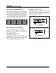
MT3855 OVEN SPECIFICATIONS VENTILATION REQUIREMENTS Installations outside the U.S. The MT3855 requires a 15 Amp, 50Hz, 1F, 230 VAC, 3 wire service consisting of L1, neutral and ground. See FIGURE 1. Use 90 C wire and size wire according to local codes. The hood should completely cover the unit with an overhang of at least 6" (15 cm) on all sides not adjaĆ cent to a wall. The distance from the floor to the lower edge of the hood should not exceed 7' (2.1 m).
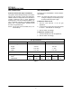
MT3855 GAS SPECIFICATIONS GAS CONNECTIONS GAS REQUIREMENTS Domestic and General Export installations The firing rate for the MT3855 is 150,000 BTU/Hr. (43.9 kW/Hr.) The gas line should be large enough to accommoĆ date the peak demand of all the gas appliances. TABLE 2 reflects a straight line, 50 foot run with no coupling restrictions and no other appliances drawing service. Gas line installations MUST conĆ form to National Fuel Gas Code NFPA 54/ANSI Z223.1 Sec. 1.4 (Latest Edition).
MT3855 ILLUSTRATED PARTS LISTS ELECTRICAL COMPONENTS NOTE: = ASAP Distributor Required Stocking Parts Ref. Part No. No. 1 1 Computer Control Kit, Closed Loop SB (Qty 1) FW525 Computer Control Kit, Closed Loop SB (Qty 1) (Reconditioned) M6474 M5635 M3175 M7427 M7202 M3347 M3348 M3490 M3491 2 3 Ref. Part No. No.
MT3855 Ref. Part No. No. 19 20 M6338 Belt, Wire S/S (Total Length 18-1/2" TB (Per Foot) MT3870 18 FT) M7272 Tensioner (After Assy., Belt MT3870 (Qty 2) 9/15/95) Fuse, Line, 22 Bodine Board, 5 AMP, 125V (Qty 1) M2316 Fuse, (Qty 1) 23 Armature, Bodine Board, 200 MA, 250V M3301 M2500 M0391 Brush Set, Bodine (Qty 1) Chain, Drive & Order (SB SpecĆ ify 2 FT or TB Specify 4 FT M0112) M6791 Guard, Drive 26 Chain SB (Qty 1) M6482 Guard, Drive Chain TB (Qty 1) * M3981 Conveyor (Before Assy.
MT3855 CONVECTION COMPONENTS NOTE: = ASAP Distributor Required Stocking Parts Ref. Part No. No. Ref. Part No. No. Description Description 33 M4224 Motor & Blower Assy. CW MT3870 (Qty 2) M1962 Hold Down, Nozzle MT3870 (Qty 1) (Before 9/15/95) 34 M4225 Motor & Blower Assy. CCW MT3870 (Qty 2) M7399 Hold Down, Nozzle MT3870 Qty 1) (After 9/15/95) M5419 Motor & Blower Assy.
MT3855 GAS BURNER COMPONENTS NOTE: = ASAP Distributor Required Stocking Parts Ref. Part No. No. 40 22132 Description Burner Assy. Complete (Specify Model & Gas Type) (Qty 1) 41 M0767 Blower Motor, Comb.
MT3855 EXTERIOR COMPONENTS NOTE: = Doors are not returnable Ref. Part No. No. M2868 M2188 Ref. Part No. No. Description Door Assembly, Pull Down S/S (used w/enclosed Greenheck hood system) (Qty 1) Handle Kit, Door 2" (used w/M2868) (Qty 1) 79 Description M7575 Extension Assy.
MT3855 Ref. Part No. No. M5485 Panel & Filter Assy. MT3855G (Qty 1) (After 11/14/95) XXXXX Control Box Cover w/ Louvers MT3855G (Qty 1) (Before 11/14/95) M6799 Control Box Cover w/ Access Door MT3855G (Qty 1) (After 11/14/95) XXXXX Ref. Part No. No.
MT3855 EXCLUSIVE TO EXPORT NOTE: = ASAP Distributor Required Stocking Parts Ref. No. Part No. 88 M2276 Burner Assy., Complete (Qty 1) 89 M4597 Motor & Blower Assy., CW MT3870 (Qty 2) 90 M4598 Motor & Blower Assy., CCW MT3870 (Qty 2) 91 M6000 Dual Solenoid/Pressure Regulator, Nat.
MT3855 MT3855 CONTROL BOX (Control Plate and/or Gas Burner Components not Shown) 10
MT3855 MT3855 GAS BURNER COMPONENTS (Control Box not Shown) 11
MT3855 MT3855 SB CONTROL PLATE ASSY (M6590) 12
MT3855 MT3855 EXTERIOR OVEN VIEW 13
CHAPTER 2 ASSEMBLY
MT3855 OVEN ASSEMBLY PROCEDURES RETURN AIR DIVERTERS AIR NOZZLES For units manufactured prior to 11/14/95 1. Install the nozzles from the center of the oven to the ends. The bottom of the nozzle must fit into the slot of the nozzle support located at the front of the oven. 1. Slide the return air diverters into the oven and clip to the lower rear of the baking cavity. The edge of the diverter should be 3" (7.6 cm) from the outside edge of the oven cavity. 2.
MT3855 CONVEYOR RACK ASSEMBLIES 4. Install the inner and outer master links as shown in FIGURE 5. For units manufactured prior to 11/14/95. 1. Slide the drive side conveyor rack assembly (with the sprocket on the end of the shaft) into the support tracks. 2. Push until the end sprocket is inserted into the control compartment. Master Link 3. Install the alignment bolt through the conveyor and control box. 4.
MT3855 FOLDING CONVEYOR ASSEMBLY END PLUGS For units manufactured after 11/14/95 1. Install the upper end plug support brackets at both ends of the oven. The conveyor must be installed from the left side (control box side) of the oven. 2. Install the upper and lower end plugs at both ends of the oven. 1. Unfold the conveyor while inserting it into the support tracks. Be careful to avoid hitting the emergency off switch on the side of the conĆ trol box.
CHAPTER 3 OPERATION
MT3855 COMPUTER CONTROLLER 1 2 9 3 8 7 6 5 4 FIGURE 1 CONTROL DESCRIPTION CONTROL OPERATION 1. DIGITAL DISPLAY - Displays the time, temĆ perature and controller related information. To turn the oven on: 1. Press and hold the ON/OFF key (2). The disĆ play reads OFF when the oven is idle. 2. The display flashes WAIT LOW SET TIME mmss. 3. The FAN and HEAT status lamps (9) light. The fans begin to run. The heat rises to the proĆ grammed temperature.
MT3855 PROGRAMMING PROCEDURES DISPLAY INFORMATION Programming the Cook Time: WAIT LOW - indicates that the present oven temperature is lower than the set point temperĆ ature. When the oven reaches the set point temperature the display changes to READY. READY - indicates that the oven is ready to acĆ cept product. SET TIME mmss - indicates the current cook time setting. HIGH TIME - indicates that the temperature is well above the set point.
MT3855 SEQUENCE OF OPERATION COMPONENT REFERENCE OPERATION NOTE: Refer to FIGURE 2 for component locaĆ tions. 1. Apply power to the oven. Program the time and temperature into the computer (1). The burner valve relay (2), blower relay (3) and main conĆ trol relay (4) energize powering up the oven. 1. 2. 3. 4. 5. 6. 7. 8. 9. 10. 11. 12. 13. 14. 15. 16. 17. 18. 19.
1 1 2 FIGURE 2 4 18 19 5 4 3 16 13 17 6 17 14 15 8 17 7 12 9 10 11 MT3855
MT3855 OVEN ADJUSTMENTS FOR COOKING TEMPERATURE EXAMPLE: A good bake time and temperature have been esĆ tablished, but more browning on top of the pie is desired. Relocate one of the blockĆoff plates" above the belt to open a few rows of holes toward the exit end of the oven. This will allow more of the superheated air to brown the top just prior to exitĆ ing the oven.
CHAPTER 4 CALIBRATION AND ADJUSTMENT
MT3855 CONVECTION BLOWER MOTORS TO CHECK MOTOR ROTATION TO CHECK LOWĆLIMIT 1. Remove the back of the oven body and verify proper motor rotation. (See FIGURE 1) 1. Turn the oven on and let it heat up to approxiĆ mately 200 F (93 C). For motor placement, the direction of rotation is viewed from the oven's rear and working from left to right, beginning at the control box. In most cases, the motor direction is referenced to the end of the shaft (EOS).
MT3855 REGULATED GAS PRESSURE 1. Let the oven run up to 510 F (266 C). justing screw located under a screw cap on the left front side of the dual regulated valve. Adjust the gas pressure by turning the screw clockwise to raise the gas pressure and counterĆclockwise to lower the gas pressure. Be sure to reinstall the screw cap; should the diaphragm rupture this cap acts as a flow limiter 2. Set the time to 7 minutes. You may now verify the operational and regulated gas pressures.
MT3855 COMPUTER CONTROL CONFIGURATION INITIATING ACCESS MODE CONFIGURATION The Cooking Computer provides a special Access Mode for setting and displaying certain computer special functions. To initiate the Access Mode place the control in the OFF state, (OFF is shown in the display when power is first applied to the control). Press the following sequence of keys to set the control to Access Mode: CLEAR 1 2 3 4 5 6 ENTER. The display will show ACCESS.
MT3855 Boost Option - (versions 2.00 or 3.00) When the controller is in the ACCESS" mode, press the following buttons: CLEAR 2 1 2 ENTER to enter the boost option. DISPLAY BOOST / MODEĆ? (Flash alternately) ACTION TAKEN Press PROG ENTER DISPLAY OPTĆ1 OPTĆ2 ACTION TAKEN or Press any numeric key to toggle between OPTĆ1 and OPTĆ2 Select OPTĆ1 to turn off boost mode.
MT3855 TEMPERATURE CALIBRATION TO ENTER THE CALIBRATION MODE 1. Press PROG/ENTER followed by ACT_TEMP. The display flashes either POS * OFFSET or NEG * OFFSET 1. Press the ON/OFF key until OFF is displayed. 2. Press CLEAR 1 2 3 4 5 6 ENTER to enter the access mode. The display reads ACCESS. NOTE: POS OFFSET is displayed if a value has been programmed in for a positive offĆ set. NEG OFFSET is displayed if a valĆ ue has been programmed for a negaĆ tive offset.
MT3855 BELT SPEED CALIBRATION CLOSED LOOP SYSTEM To enter the calibration mode: 3. ENTER ACTUAL TIME - Place an object on the belt. Note the time from entrance to exit. Enter the actual measured time. 1. Press the ON/OFF key until OFF is displayed. 2. Press CLEAR 1 2 3 4 5 6 ENTER to enter the Access mode. The display reads ACCESS. 4. ENTER TEST TIME - If the actual measured time is not within 5 seconds of the test time, reĆ peat the belt verification test to obtain better accuracy.
MT3855 OPEN LOOP SYSTEM - SINGLE BELT To enter the calibration mode: The belt will travel very slowly during this part of the calibration procedure. To minimize the time spent on STEP-2, measure off 10" on the conveyor support. Place an object on the belt and note the travel time for the 10" measured distance. 1. Press the ON/OFF key until OFF is displayed. 2. Press CLEAR 1 2 3 4 5 6 ENTER to enter the Access mode. The display reads ACCESS. 3.
MT3855 OPEN LOOP SYSTEM - TWIN BELT To enter the calibration mode: The belt will travel very slowly during this part of the calibration procedure. To minimize the time spent on STEP-2, measure off 10" on the conveyor support. Place an object on the belt and note the travel time for the 10" measured distance. 1. Press the ON/OFF key until OFF is displayed. 2. Press CLEAR FRONT BELT, FRONT BELT, FRONT BELT, PROG/ENTER to enter the AcĆ cess mode. The display flashes ACCESS. 3.
MT3855 MOTOR CONTROL BOARD ADJUSTMENT High/low speed motor control board adjustĆ ment for 180 and 130 volt DC motors COMPUTERIZED OVENS 130 Volt System NOTE: The motor control board is located on the slide out control panel. High Speed Motor Adjustment: For closed loop systems follow Belt Speed VerificaĆ tion through STEP 5 (see page 6). For open loop systems follow Belt Speed Calibration through STEP 2 (see page 7 or 8). 1.
MT3855 Minimum Speed Torque (current) limiting adjustment (DO NOT ADJUST) Maximum Speed Acceleration Adjustment Switches 2,4,5,6,7 ACC Yellow or Violet (pin 12) Orange or Gray (pin 10) Line Fuse ON DIP Switch on early models only TP2 Socket J1 Blue Gray TORQ MIN TP1 Test Points Blue (pin 8) Violet MAX REG Regulation Adjustment Armature Fuse FL TB1 Speed Pot L N A1 NOTE: Colors may vary between early ovens.
MT3855 RERATING THE APPLIANCE Due to the lack of oxygen at higher elevations, the unit may need to be rerated. (The orifice size may need to be adjusted to accommodate different air pressures at higher elevations.) If not rerated, inĆ complete combustion may occur releasing AldeĆ hydes and CO or Carbon Monoxide. Any of these are unacceptable and may be hazardous to the health of the operator. Use the following formulas to calculate the correct orifice: 1. 2.
MT3855 CHECKING THE FIRING RATE Method #1 Locate the time observed in STEP 2. Move across the table to either the 1/2 cu. ft. or the 2 cu. ft. column to find the gas input to the burner. 1. Turn off all other appliances on the line. Press the ON/OFF key on the unit to call for heat. 2. Using either the 1/2 cu. ft. or the 2 cu. ft. dials, note the time it takes the indicator to complete one revolution. See FIGURE 4. 3. Use the following formula to determine the firĆ ing rate of the meter.
MT3855 This page intentionally left blank.
CHAPTER 5 TROUBLESHOOTING
MT3855 DC DRIVE SYSTEM POSSIBLE CAUSE(S) SUGGESTED REMEDY Symptom #1 - Conveyor Belt will not run Oven in OFF mode. Turn to ON position. Loose computer controller cord connection. Adjust and retighten cables and set screws. Time not programmed into computer. Program in a cook time. See page 2 of the OperaĆ tion section. Emergency stop switch on OFF. Pull switch out to ON. Control circuit breaker tripped. Reset breaker. Belt hooked on something in oven.
MT3855 COMPUTER CONTROL SYSTEM POSSIBLE CAUSE(S) SUGGESTED REMEDY Symptom #1 - Computer controller displays: PROBE Ć OPEN Ć PROBE Ć SHORT and alarm buzzer sounds Internal problem with computer controller. Verify display integ. in the 2nd level programĆ ming. If the controller has been programmed the computer may need to be replaced. Loose connections at computer controller. Tighten connections. Shorted or open RTD probe.
MT3855 HEATING SYSTEM POSSIBLE CAUSE(S) SUGGESTED REMEDY Symptom #1 - Burner will not fire Oven in OFF mode. Turn to ON position. Emergency stop switch on OFF. Pull switch out to ON. Control circuit breaker tripped. Reset breaker. Combustion motor not running. Check transformer for primary and secondary voltage. Check main control and burner valve relays to see if closed. Check relay in combustion burner box. If bad reĆ place relay.
MT3855 POSSIBLE CAUSE(S) SUGGESTED REMEDY Symptom #2 - Oven will not reach desired temperature Gas pressure to oven is too low. Contact local gas representatives. Top air plates missing. Install air plates. Faulty RTD probe. Use the chart on page 6-10 of the Technical ApĆ pendix to determine if probe is bad. Replace if necessary. Blower motor(s) running backward. Verify voltage to motor. If voltage is present, reĆ place the motor or start capacitor.
MT3855 CONVECTION SYSTEM POSSIBLE CAUSE(S) SUGGESTED REMEDY Symptom #1 - Blower motor(s) not running Oven in OFF mode. Press ON/OFF key. Emergency stop switch on OFF. Pull switch out to ON. No power to oven. Verify power to motor(s). If there is voltage presĆ ent, replace the motor. If voltage is not present, check the motor contactor. Motor circuit breaker tripped. Replace fuse. Determine amp draw. Faulty start capacitor. Replace capacitor. Motor(s) burnt out.
MT3855 POSSIBLE CAUSE(S) SUGGESTED REMEDY Symptom #3 - Hood system does not operate when oven is on Fan exhaust/supply problem. Contact HVAC service. Defective interlock circuit. Replace auxiliary contactor. Symptom #4 - Blower motor running backward Motor off by thermal overload (other fans forcing blower to spin). Determine if the cooling blower (or fans) are operĆ ating. If not, verify voltage to the cooling blower. If voltage is present, replace the cooling blower motor.
MT3855 This page intentionally left blank.
CHAPTER 6 TECHNICAL APPENDIX
MT3855 INTERMITTENT IGNITION SYSTEM PRINCIPLES OF OPERATION In the IID system the probes exposed to the pilot flame are the Flame Sensor and the Pilot Burner Hood. Since the surface area of the pilot hood is larger than the flame sensor, the current rectificaĆ tion process takes place. Current is conducted from terminal 4 at the control through the flame sensor cable to the flame sensor.
MT3855 SERVICE PROCEDURES To Measure DC Flame Sensing Current: Service the IID system as follows: 1. Turn off the power supply to the ignition conĆ trol. 1. Make certain the thermostat contacts are open. 2. Disconnect the flame sensor cable from termiĆ nal #4 on Johnson units or terminal #1 on LanĆ dis & Gyr units. 2. Check for proper supply voltage at primary and secondary of system transformer. 3. Set the selector switch on the meter to microĆ amp scale.
MT3855 REPAIRING THE ELECTRONIC IGNITION 5. Install the Y75 sensing probe into the pilot burner. Reconnect the sensing probe cable. The connections to the sensing probe and control terminal must be secure. SYSTEM Flame Sensing Current Maintenance: The flame sensor is made of carbon steel and subĆ ject to contamination and oxidation buildup. Any buildup on the sensor can add enough resistance to drop the signal below the required minimum. Carbon and oxidation can also build up on the pilot hood.
MT3855 SERVICING THE INVENT HOOD ILLUSTRATED PARTS LIST QTY PART DESCRIPTION (SEE FIGURE 3) ITEM 1 AMU/Exhaust Manifold/Duct Connection 1 1 AMU Duct Extension, 10 x 18 x 9"h 2 1 Exhaust Duct Extension, 9 x 18 x 12"h 3 1 AMU Support Bracket, Right 4 1 AMU Support Bracket, Left 5 1 Lower Front AMU Panel 6 1 Middle Front AMU Panel 7 1 Upper Front AMU Panel 8 2 Filter Trough/Receptacle 9 2 Filter,10x16" 10 2 Filter, 10 x 20" 11 1 Vertical Exhaust Manifold, Right 12 1 Ver
MT3855 14 2 15 3 20 1 16 9 8 17 12 7 19 4 10 18 6 13 11 5 FIGURE 3 CLEANING AND MAINTENANCE They will scratch and mar the exterior finish. Rinse the panels in warm water and dry them. 5. Reinstall the Filter Trough/Receptacles, Filters and End Enclosures. CAUTION! The oven and the ventilation system get hot during operation. Allow the oven/ ventilation system assembly to cool so as to avoid possible injury. EVERY THREE MONTHS 1.
MT3855 Wipe out the exhaust channel portion of the SERVICING ACCESS AMU/Exhaust Manifold/Duct Connection (item 1) assembly. Brush and clean the guards of the oven cooling fans. For servicing the oven, disconnect the gas and electric services from the oven. Use the following procedure to move the oven/ventilation system asĆ sembly for maintenance. 7. Dry the parts and return them to their positions.
MT3855 PRESSURE CONVERSION PRESSURE CONVERSION CHART in/H2O P.S.I in/Hg mm/H2O mm/Hg kg/cm2 bar mbar Pa kPa 1 .0361 .0735 25.41 1.868 .0025 .0025 2.489 248.9 .2489 2 .0722 .1470 50.81 3.736 .0051 .0050 4.978 497.8 .4978 3 .1083 .2205 76.22 5.604 .0076 .0075 7.467 746.7 .7467 4 .1444 .2940 101.62 7.472 .0102 .0099 9.956 995.6 .9956 5 .1804 .3673 127.0 9.335 .0127 .0124 12.44 1244 1.244 6 .2165 .4408 152.4 11.203 .0152 .0149 14.93 1493 1.
MT3855 in/H2O P.S.I in/Hg mm/H2O mm/Hg 29 1.047 2.132 736.8 54.18 30 1.083 2.205 762.2 31 1.119 2.278 32 1.155 33 kg/cm2 bar mbar Pa kPa .0736 .0722 72.19 7219 7.219 56.04 .0761 .0747 74.67 7467 7.467 787.5 57.91 .0787 .0772 77.15 7715 7.715 2.352 812.8 59.77 .0812 .0796 79.63 7963 7.963 1.191 2.425 838.2 61.63 .0837 .0821 82.12 8212 8.212 34 1.227 2.498 863.5 63.49 .0862 .0846 84.60 8460 8.460 35 1.263 2.571 888.9 65.36 .0888 .
MT3855 CONVERSION FACTORS COMMON CONVERSION FACTORS PRESSURE CONVERSIONS FACTORS Multiply By To Get Multiply By To Get BTU/hr .001054804 MJ/hr in/H2O 0.0361 P.S.I. .0002931 kW 25.41 mm/H2O .29285 W 1.868 mm/Hg .0372589 MJ/m3 .0025 kg/cm 2 8.905102 kcal/m 3 .0025 bar MJ/hr 948.0434279 BTU/hr 2.489 mbar Mj/m 3 26,839225 BTU/ft 3 248.9 Pa kW 3414.71732 BTU/hr .2489 kPa ft3 .02832 m3 27.71 in. H2O ft2 .09290304 m2 2.036 in. Hg inches 25.40005 mm 703.
MT3855 COOKING COMPUTER - TEMPERATURE VS RESISTANCE T/F Res/Ohms T/F Res/Ohms T/F Res/Ohms T/F Res/Ohms 70 541.12 230 711.43 390 877.15 550 1038.293 75 546.51 235 716.68 395 882.26 555 1043.255 80 551.9 240 721.92 400 887.36 560 1048.212 85 557.28 245 727.16 405 892.46 565 1053.165 90 562.66 250 732.4 410 897.55 570 1058.113 95 568.04 255 737.63 415 902.63 575 1063.057 100 573.4 260 742.85 420 907.72 580 1067.997 105 578.77 265 748.